|
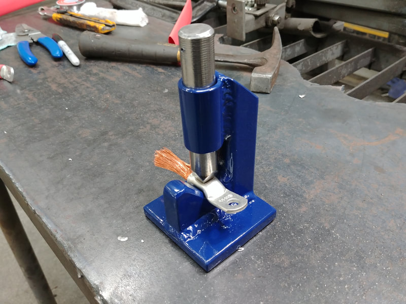
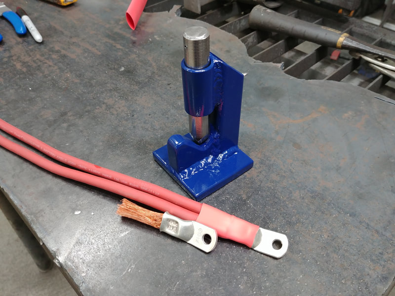
Hey folks. I've just got a quick build video for you today. In this one, I make a hammer crimper for crimping lugs to the cables that I'm using for the electric crosskart battery.
A hammer crimper is a pretty common tool and is reasonably affordable, costing around $30-$50. But, most of you know what I'm about. Why spend the $ and wait 2-3 weeks for delivery when I can make it out of scraps in 20-30 minutes and get straight to work crimping cables? So let's do it.
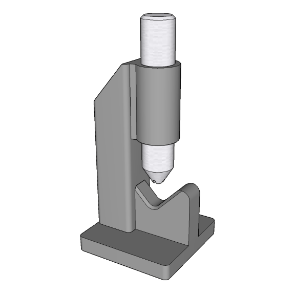
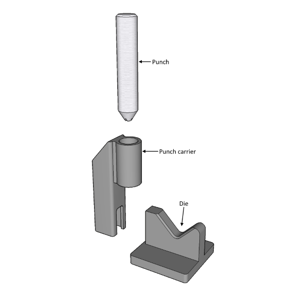
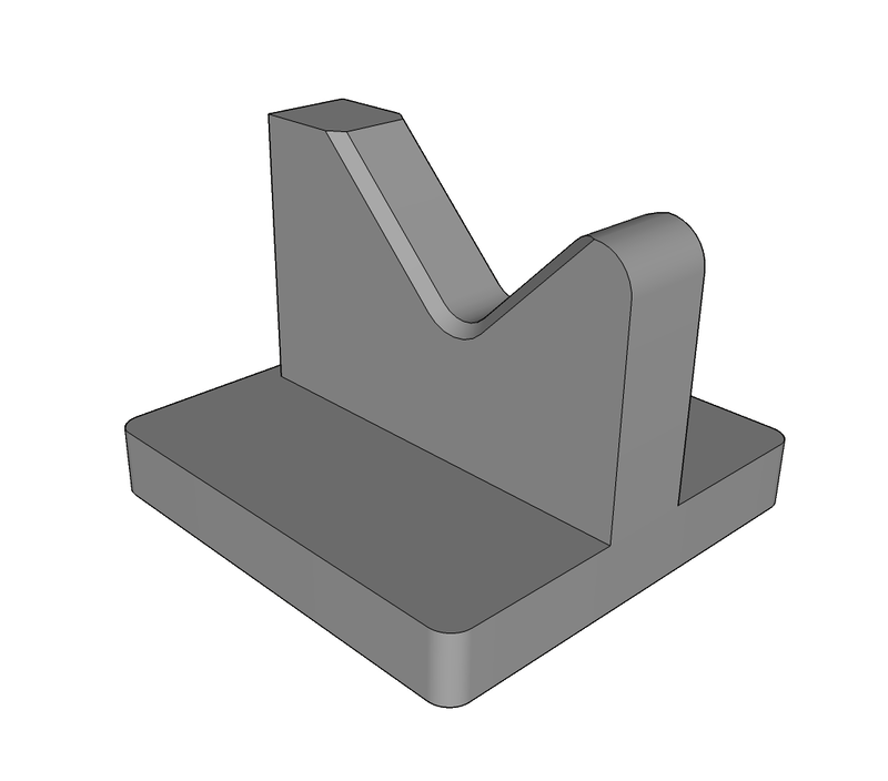
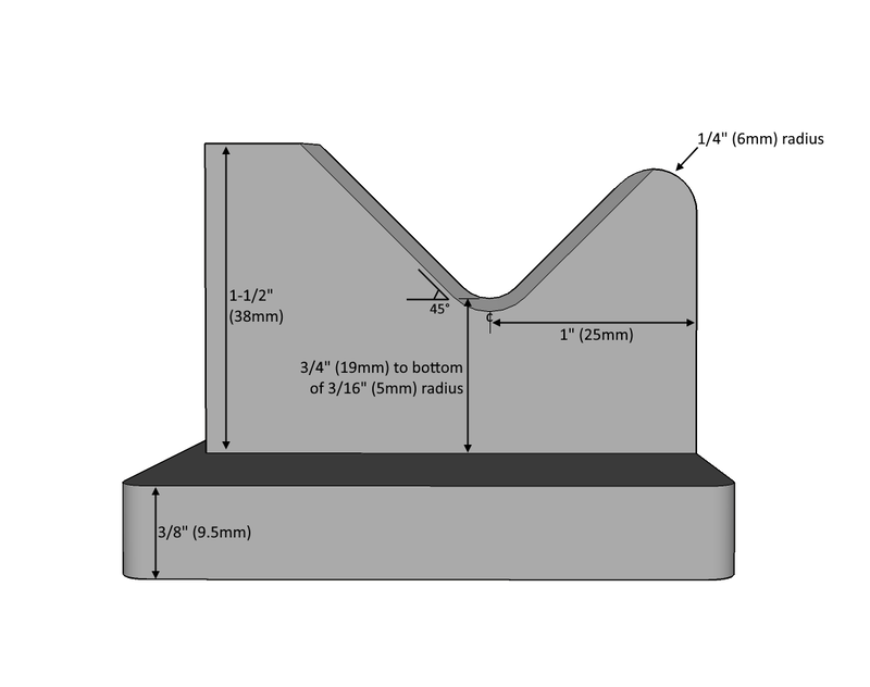
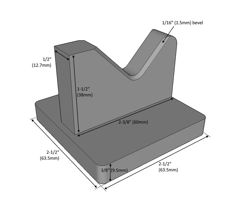
The design is really simple, I almost don't need to explain anything about it, but I will just to say I did. The first thing that I did was mark out the die profile onto a piece of 1/2" mild steel flat bar, then center punched and drilled a 3/8" diameter hole where the lug will rest on the form as it's crimped. I then made two cuts at 45° angles on either side of the 3/8" hole cut to form a 'birds mouth' and beveled the edges slightly with an angle grinder. I chose 1/2" steel because it's a good thickness for the length of the 1/0 lugs that I'll be crimping - it provides a good surface area to support the bottom tube portion of the lug while it's being hammered on without affecting the bolt flange. A person could crimp 4 awg cable or greater with this tool, though a punch with a narrower end will be necessary for smaller gauges.
After the form was cut and drilled, I made a simple 2.5" square base to weld it to using 3/8" mild steel plate.
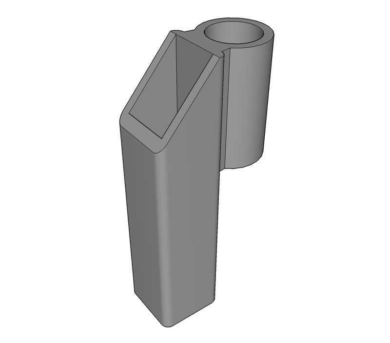
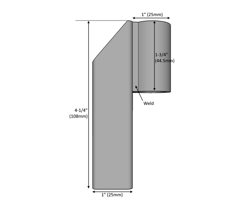
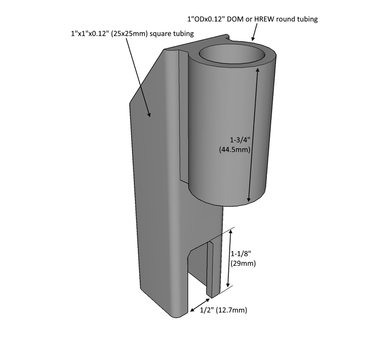
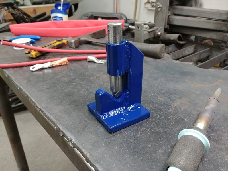
Next, I cut up an old rusty piece of 1x1" square tubing and 1"x0.12" HREW round steel tubing as shown below. These will be the carrier, so to speak, for the punch (plunger, whatever you want to call it). The square tubing was notched in the bottom to receive the form base, but not before it was welded to the round tubing. The only thing that's important to ensure is that the center of the round tubing ends up centered with the form below it, otherwise the crimping will be buggered up and off-centered, and may not provide sufficient holding power on the cable to prevent them from pulling apart later.
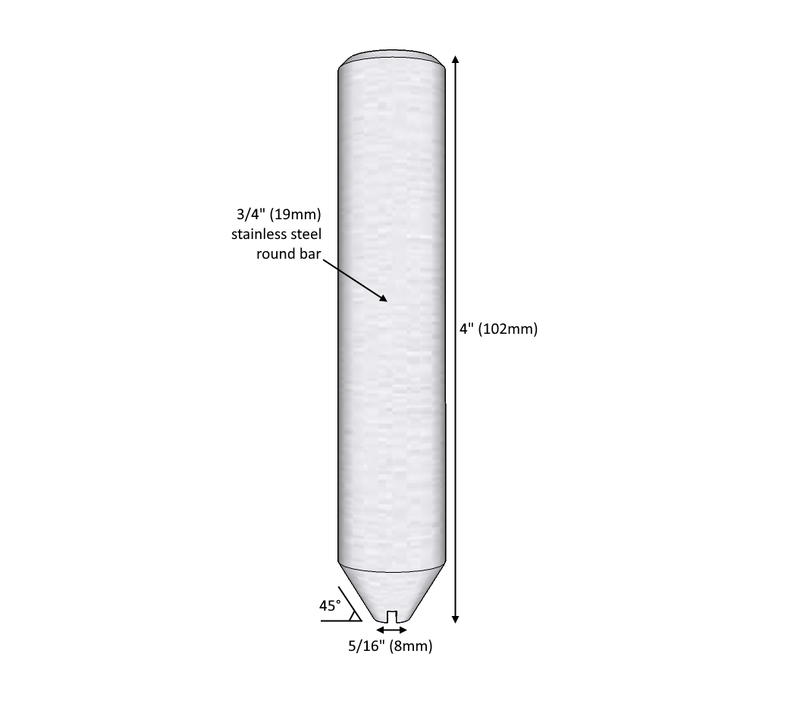
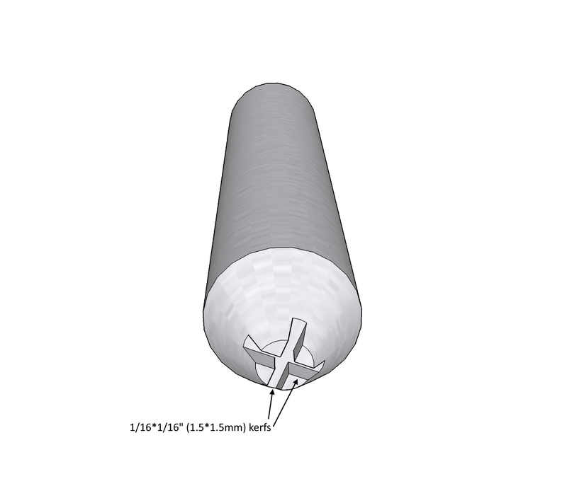
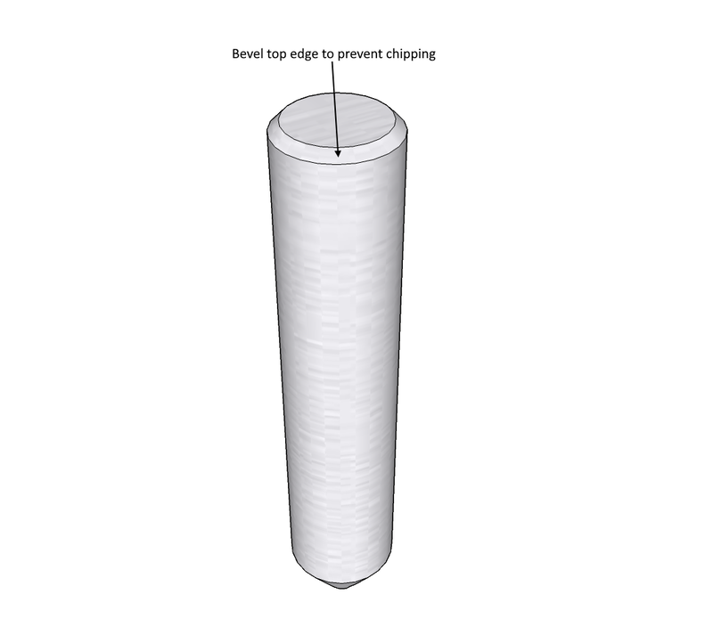
The super easy bit was making the punch. It's just a 4" long piece of 3/4" stainless steel round bar with 45° bevels on the bottom narrowing to a 5/16"x5/16" square end that has two crisscrossing kerfs cut into the face, approximately 1/16" deep. Resembling the end of a fat, inverted Phillips head screwdriver. These kerfs will transfer into the lug when it's crimped to provide better gripping power on the cable. The top end of the punch was beveled slightly to help prevent chipping the edges when it's being hammered.
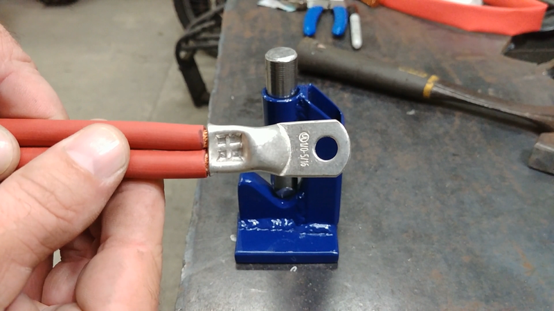
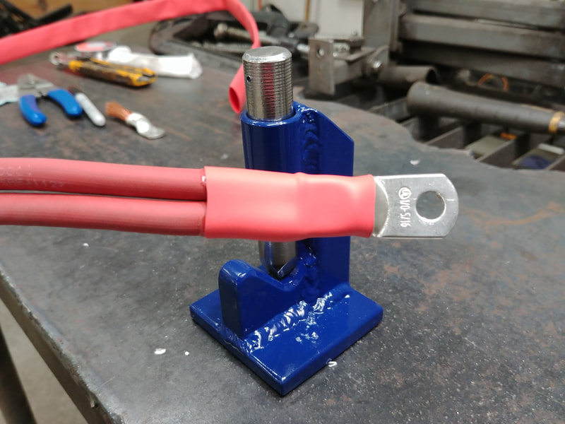
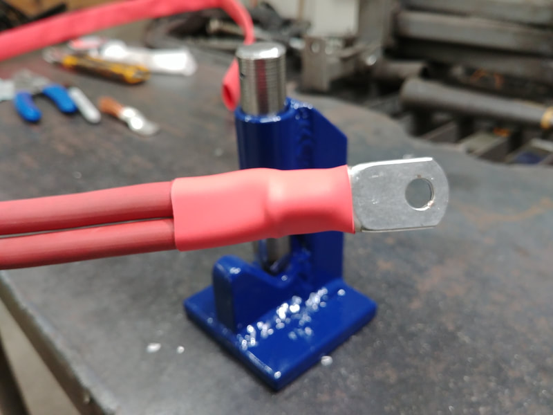
A coat of spray paint later and the crimper was done. It works great for crimping two 4 awg cables into a 1/0 lug (the reason why I'm using two cables instead of one is explained in the crosskart blog). A few good whacks with a 20oz hammer is all it takes. The end result looks and functions as I would expect. I haven't load tested them, of course, but if the strands are crushed to the point of resembling a solid piece of copper and I can't pull them apart with a pair of pliers, then there's a pretty good chance the connection is fine and they won't work themselves loose in the battery case.
A few side notes about crimping copper lugs to battery cables. There seems to be some debate about whether to solder the connection or not. Some people believe solder is the only way, while others believe crimping is superior. There's nothing wrong with soldering your lugs, if you have the means to provide enough heat to do so without damaging the cable insulation. That's the problem with soldering. It makes a solid, sealed connection that won't corrode (as long as you use rosin flux and not acid flux), but the thicker the cable is the more heat it takes to solder until you get to a point where a standard soldering iron isn't up to the task. I'm pushing it with the 4 awg cable and 200W iron. If I had to use 1/0 cable, I would probably need to use a blow torch on the lug and cable end - I don't think that would work out too well if I expect to keep the insulation as close to the joint as possible.
Crimping will provide a bond that's as strong if not stronger than solder in some cases, but if tinned copper cable isn't used (which is expensive), then some precaution needs to be taken to prevent the cable from corroding later, which all copper does when it's exposed to air. You can sand it clean and shiny, but within a year it will turn green and likely affect the connection if the mating surfaces aren't married perfectly. The first thing to do to prevent this is to use tinned copper lugs, not bare copper lugs. Tinned copper lugs have, of course, a coating of tin on them to seal the copper from the air. The next thing you should use to protect the connection is heat shrink tubing. But not just any kind - you need the stuff that has a layer of glue on the inside surface. It's like hot glue, when heated this will make the final seal between the shrink tubing and the cable/lug connection. That's all you need to do. Most electricians just crimp their battery cable lugs. When done properly you can count on the connections to last longer than the battery itself. I'll have the next video for the crosskart build series uploaded in roughly a week, give or take a couple of days. I'll be assembling the P groups for the 11.5 kWh LiFePo4 battery and test fitting them in the crosskart cabin with aluminum cases and the new bucket racing seat from Scat.
0 Comments
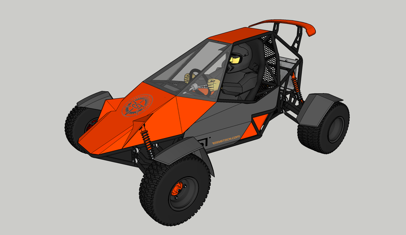
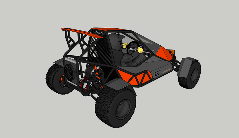
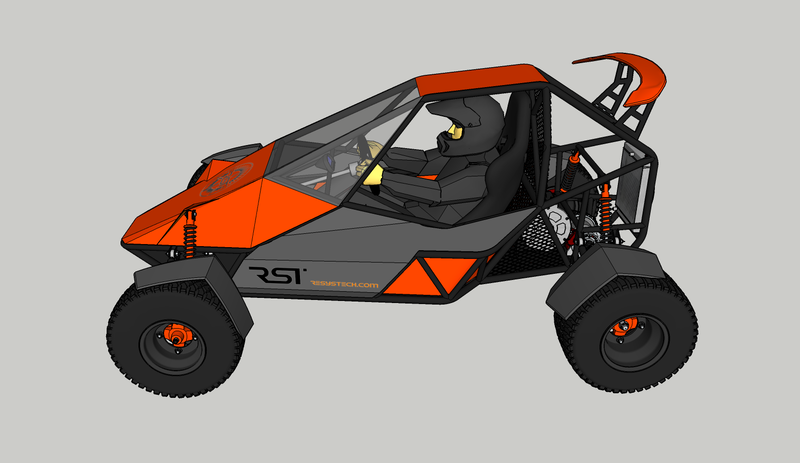
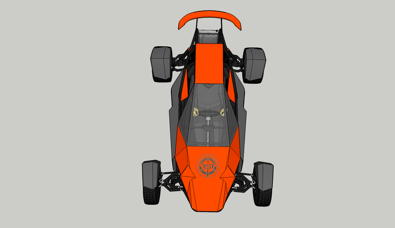
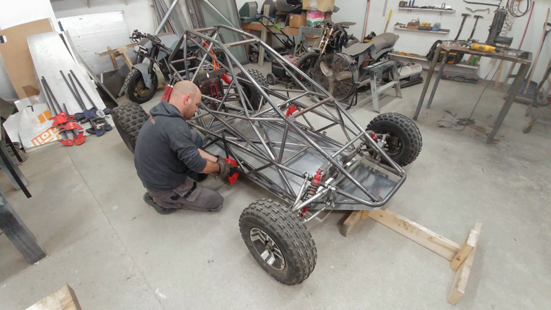
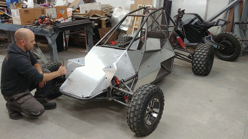
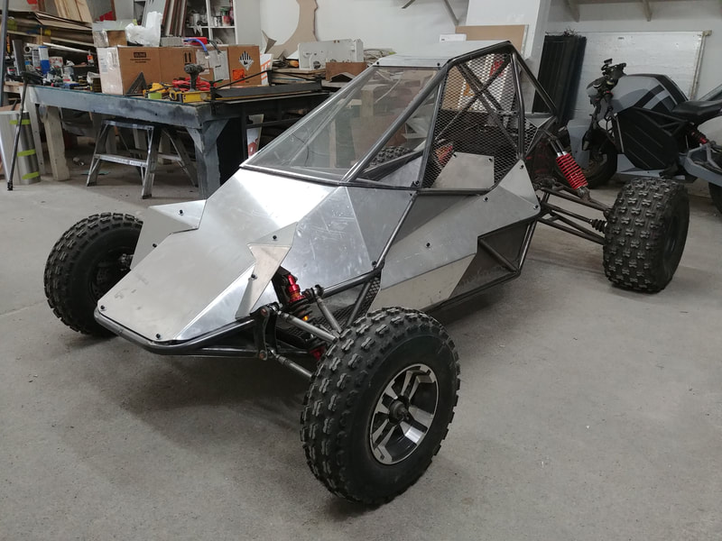
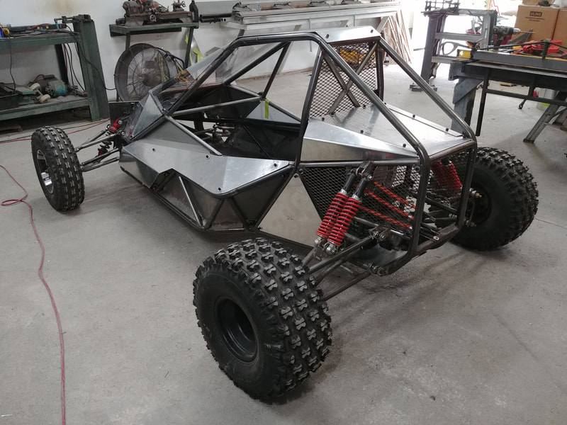
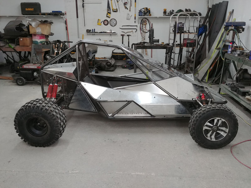
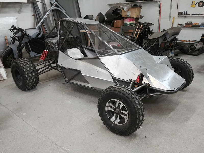
In this video I make the body panels for the electric crosskart. I chose to use 1/8" thick aluminum for most of the job, and also some 20 gauge steel. I originally wanted to use 1/16" aluminum, but the local supply store didn't stock it and it would have been almost twice the cost to order online. I think the 1/8" panels added an extra 25-30 lbs, but they're strong. I'm glad I used it. I should note that using all metal panels effectively turned the cabin into a giant drum, so I intend to make anti-vibration washers from 1/4" silicone rubber to install between all of the bolt-on panels during final assembly to help minimize the noise on the trail. The CAD pics below show what the crosskart will ultimately look like when it's finished.
Because aluminum sheet is relatively expensive, I wanted to limit waste as much as possible, so I started with the larger panels first and finished with the smaller panels that I could cut out of the waste left over. The first panel that I made was the skid plate under the chassis. This crosskart is technically an off road buggy so there needs to be some protection underneath to deflect rocks, keep the chassis crossmembers from getting hung up on something in the trail, and keep me protected too. But it's not a rock crawler, so the aluminum should be strong enough for the job.
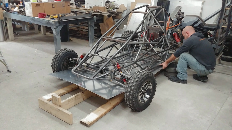
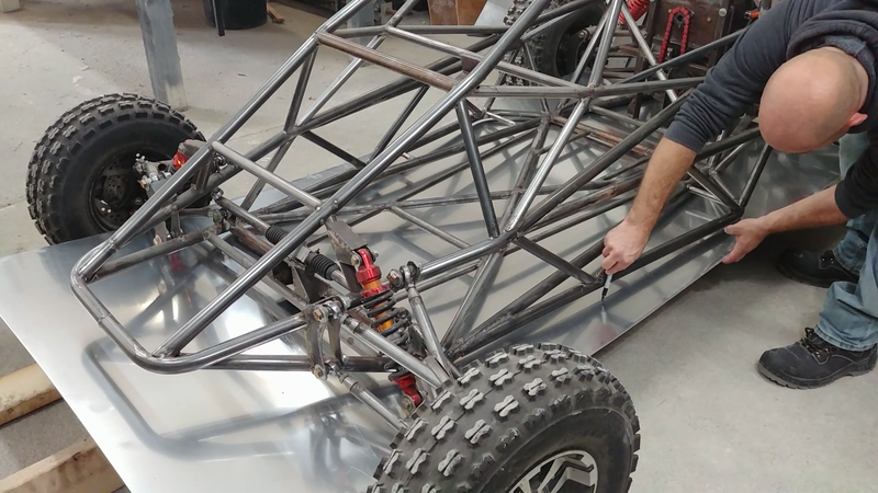
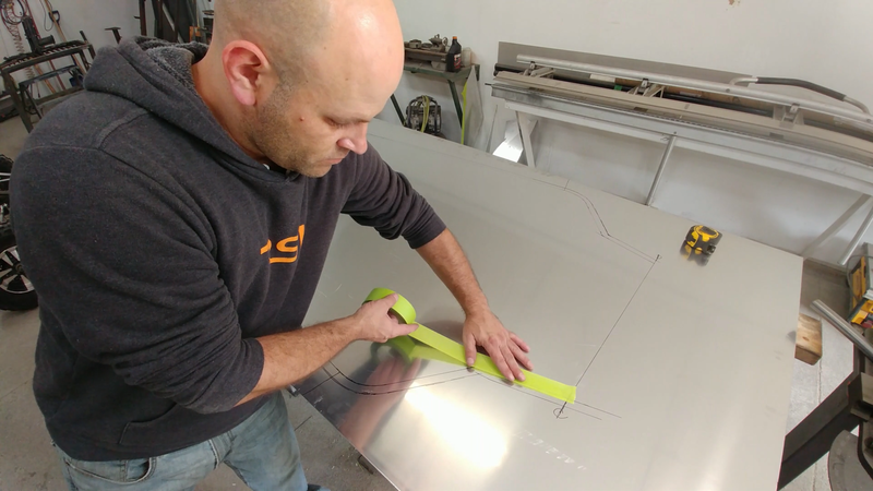
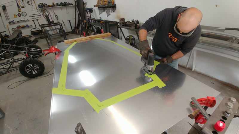
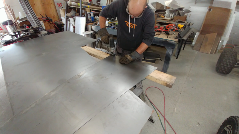
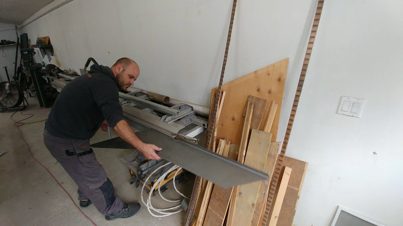
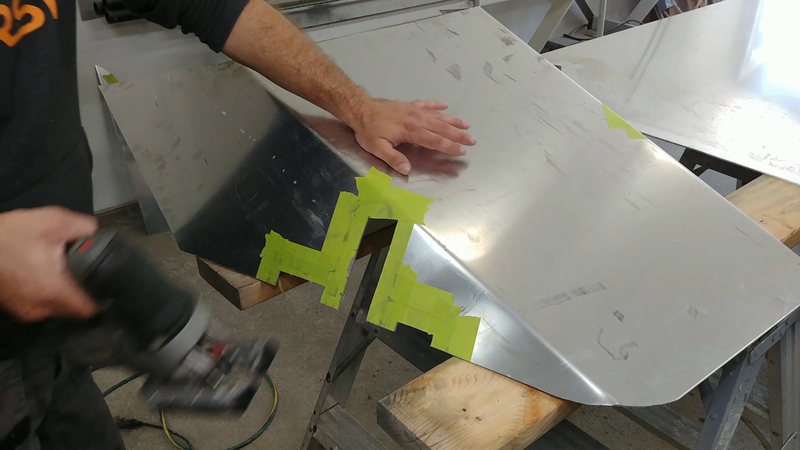
To get the profile of the chassis bottom, I wedged and clamped the aluminum sheet to the chassis and traced the perimeter with a marker. I then taped over the mark and on either side of it with masking tape before cutting it with a jigsaw. This helps keep the aluminum from getting scratched up by the shavings getting caught under the jigsaw base. The adhesive on the tape also keeps the blade lubricated when it heats up and prevents the aluminum from sticking to the blade. Steel is relatively easy to cut with a jigsaw, but aluminum is so soft that it gums up on the blade until it jams up and becomes impossible to cut. Some people like to use cutting oil or WD40 to keep the blade lubricated, which works fine but makes a mess. Lapping the masking tape over the line a little bit works just as good at lubricating the blade, and there's no mess to wipe up after.
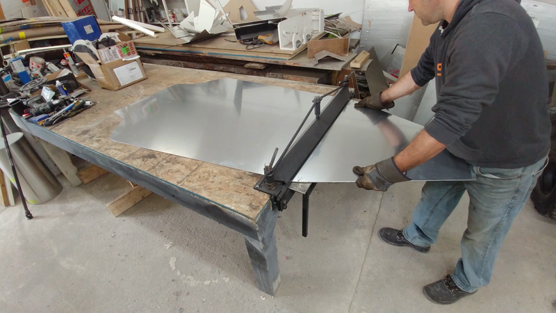
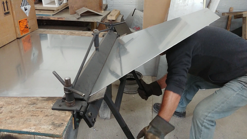
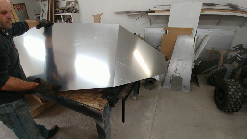
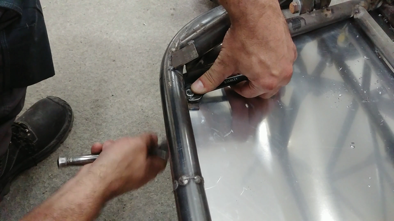
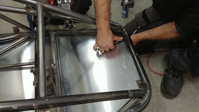
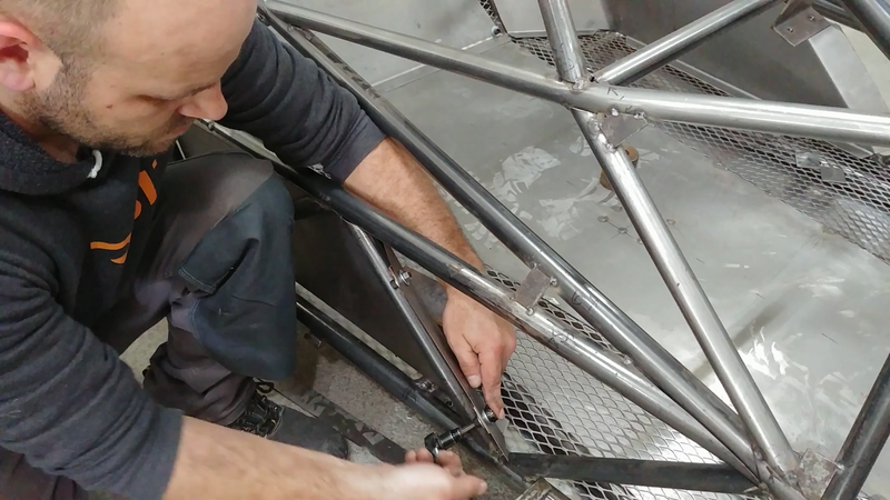
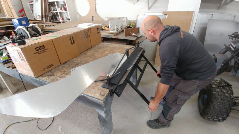
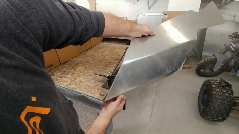
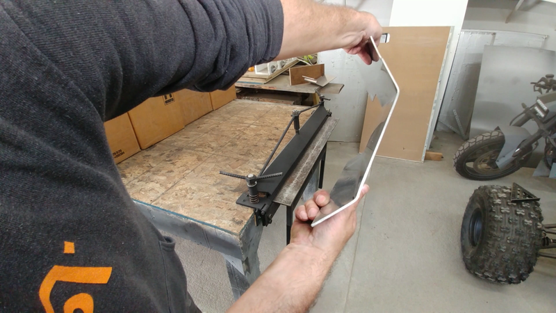
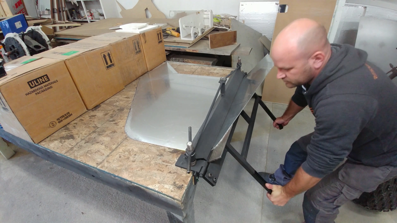
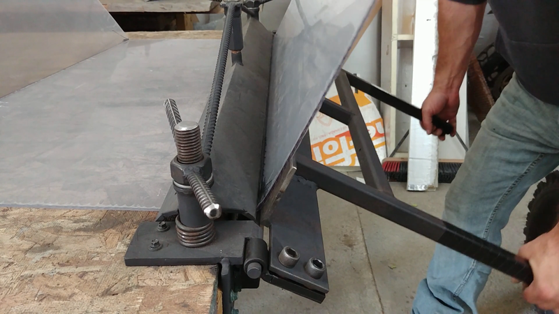
After the skid plate was cut, I sanded and filed the edges to remove the burrs, then clamped it in my new sheet metal brake that I built a few weeks ago, and bent the front end of the plate to match the angle on the front of the crosskart. Then I clamped the plate to the bottom of the chassis again to check the cut and bend, and fastened it to the mounting brackets using 5/16"x1" socket cap screws and lock nuts.
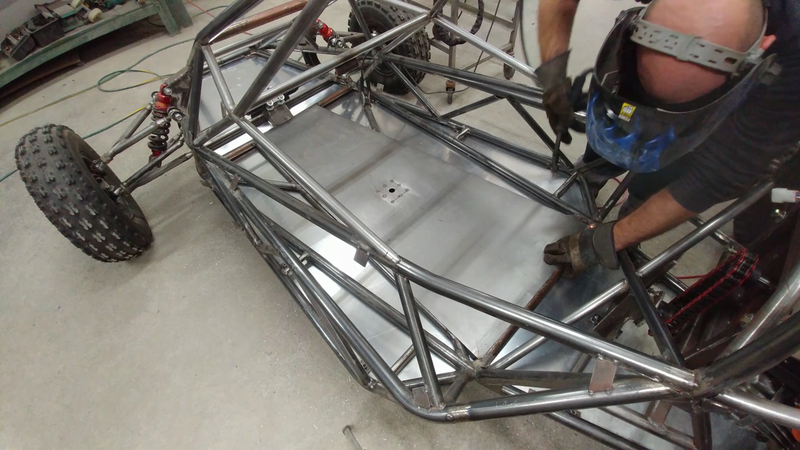
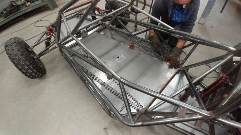
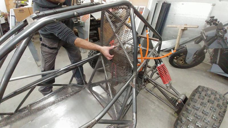
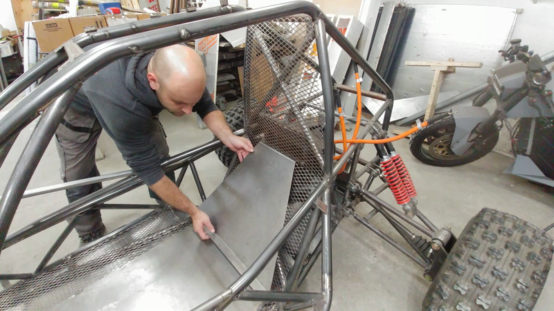
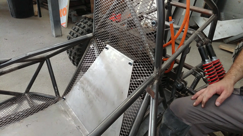
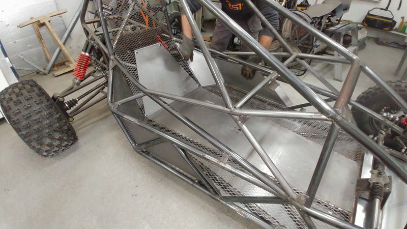
Next, I needed a floor pan of some sort to create a level surface to mount the battery boxes and seat. I didn't want to use the thick aluminum but I didn't want to cover the entire floor in 20 gauge steel, either, because it would have been just as heavy. Instead, I laid out where the battery boxes would be located on either side of the seat, then cut 16 gauge expanded steel sheet to fasten over the area that the batteries will be and used the 20 gauge (solid) steel sheet to cover the rest of the floor under the seat and throttle/brake pedal area. The expanded metal weighs a lot less than than the steel sheet, and it will allow a bit of airflow beneath the batteries to help keep them cool. I welded a 1/8" steel plate between the crossmembers in the seat area to provide a solid structure to bolt the seats to, before welding the rest of the floor in place. I also drilled/cut holes in the floor pan where I needed access to the skid plate bolts.
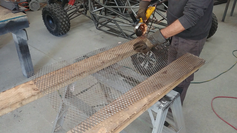
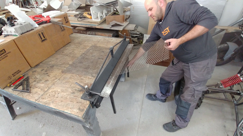
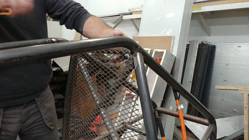
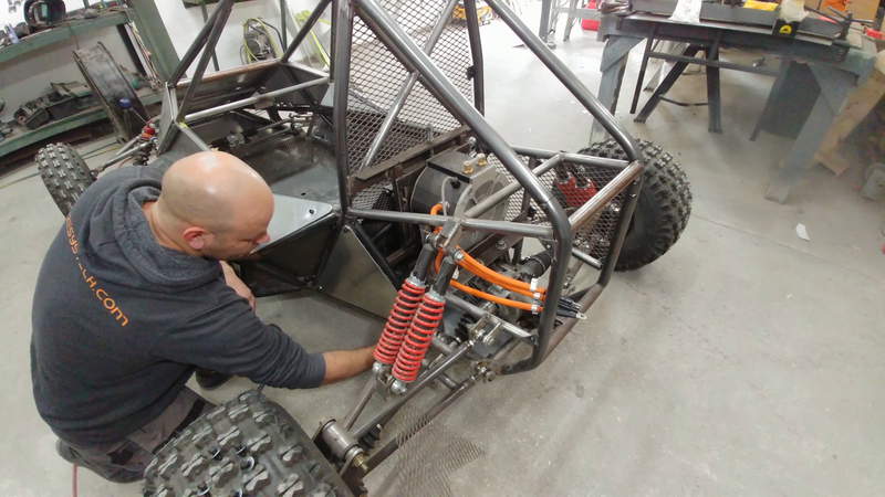
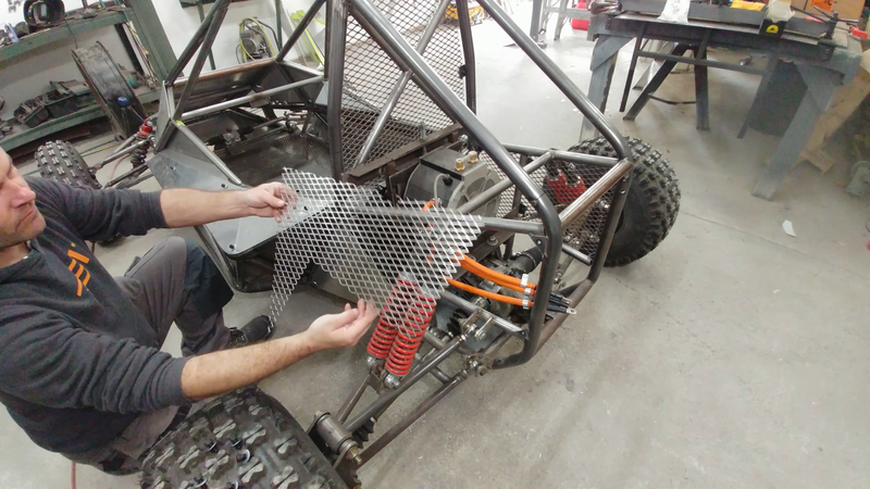
Once the floor was finished, I cut and bent a piece of expanded metal to fasten to the chassis behind the seat. This, combined with the steel plate guard, will offer some protection against the chain and the rest of the drivetrain when I'm driving, but also allow some airflow through to the back of the crosskart where the motor and controller are located. The motor will be liquid cooled by a 12V pump and radiator mounted at the back end of the chassis, but the controller is air cooled so the more airflow I can get back there without exposing it to water, the better.
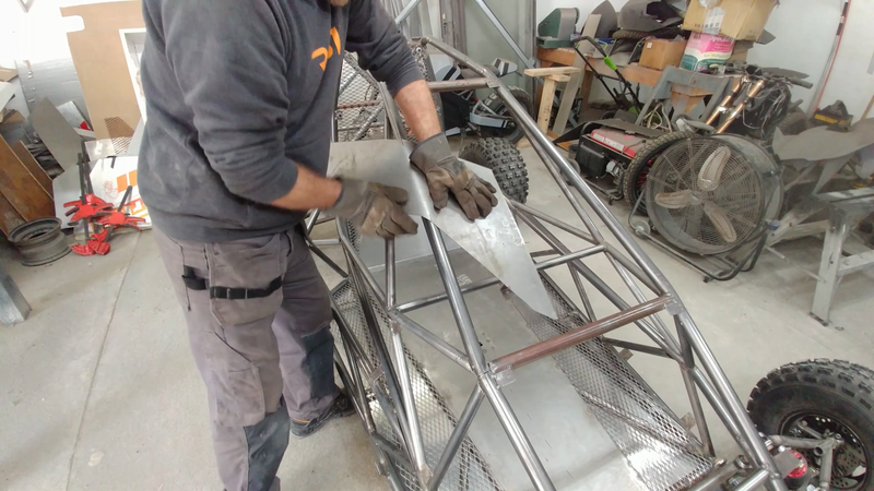
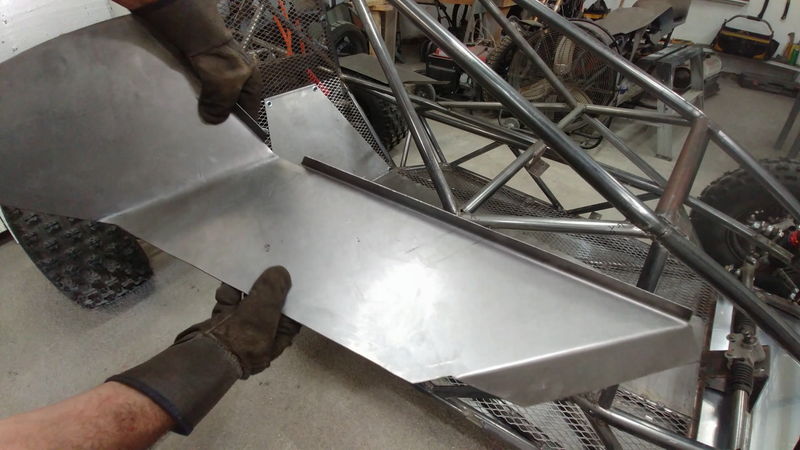
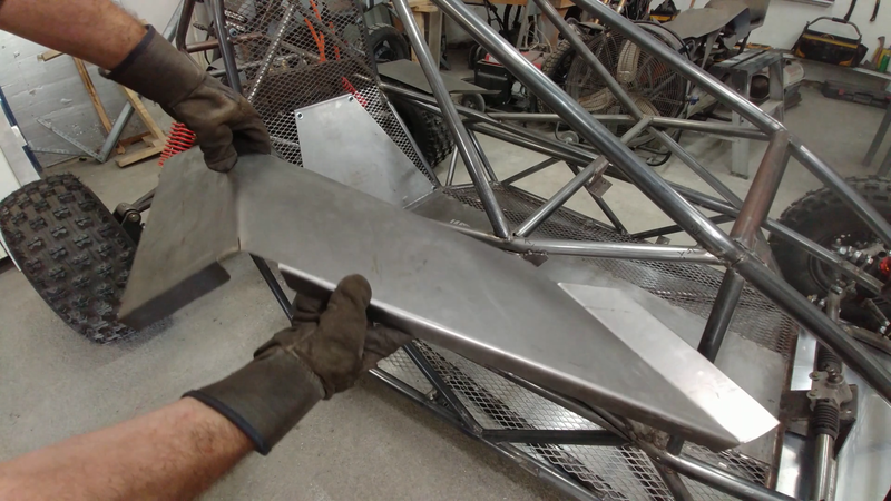
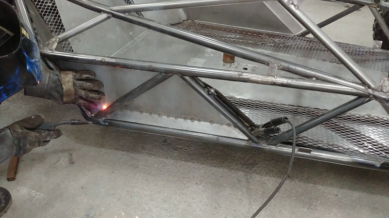
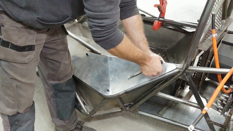
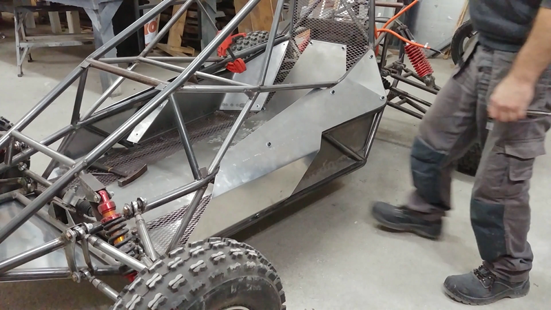
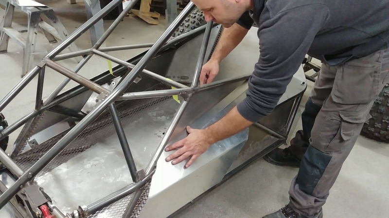
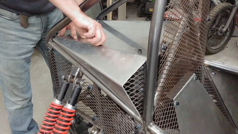
The side panels were made in separate sections. The first were made from steel sheet and formed to fit inside the cabin (at the back half), so that the tubing is exposed on the outside but the panels still protect me and the battery from rocks kicked up by the tires. I did this because I like the look of the tubing and didn't want to cover all of it. I added some angled pieces near the bottom edge to help keep dirt from collecting on the bottom tubes. These were welded to the side panels only, and the panels were bolted to the chassis so they can be removed if/when needed.
The other panels were made from aluminum sheet and formed to fit on the outside of the chassis, with an air intake port bent into the profile as well. This intake will force air behind the battery boxes to help keep them cool. The air will exit through the expanded metal behind the seat. The intake ports were also fitted with expanded metal at the openings to help keep debris from entering the cabin. A polyester filter material will be used behind the expanded metal to keep out the dust.
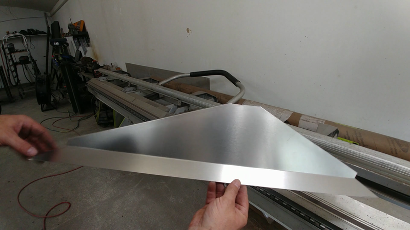
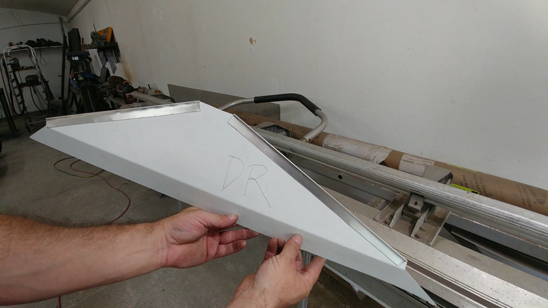
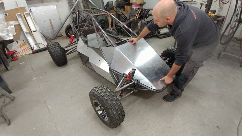
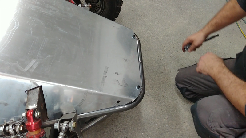
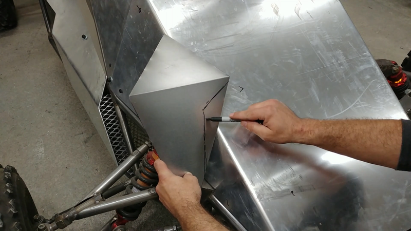
I bent two more smaller aluminum panels to finish the sides just under the windshield. These were made with thin aluminum sheet to save weight since they're just there to help block the wind. Then I bent the hood and notched the edges around the suspension mounting brackets, and bolted it to the chassis. I should note that I made templates with aluminum flashing for marking and cutting all of the complicated panels. Cardboard would have been cheaper, but I had none in the workshop and the aluminum templates will last longer anyway, in case I damage something later in the future and need to make a replacement panel.
I also bent two fenders to mount to the hood over the front suspension to help streamline that area and keep water out.
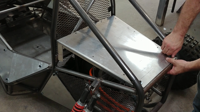
I then moved on to closing in the back of the chassis will more aluminum and expanded metal to protect the chain, motor & controller wiring, radiator, etc. I installed an aluminum cargo bed as well. It's not much but it can fit a backpack and a small cooler. Good enough for a day on the trail. It also doubles as a heat sink, since the controller will be mounted to it underneath to keep it out of the rain, too. I thought the controller was sealed and IP67 rated when I bought it, but I misread the specs. It's IP54 rated, so it can take some splashing from the tires or a garden hose, but it can't be submerged. Mounted high under the cargo bed next to the motor is a good place to keep it dry and cool and minimize the transmission wires. On each side of the cargo bed, I installed more forced air intake ports to help drive air by the controller - polyester filter material will be used here, as well.
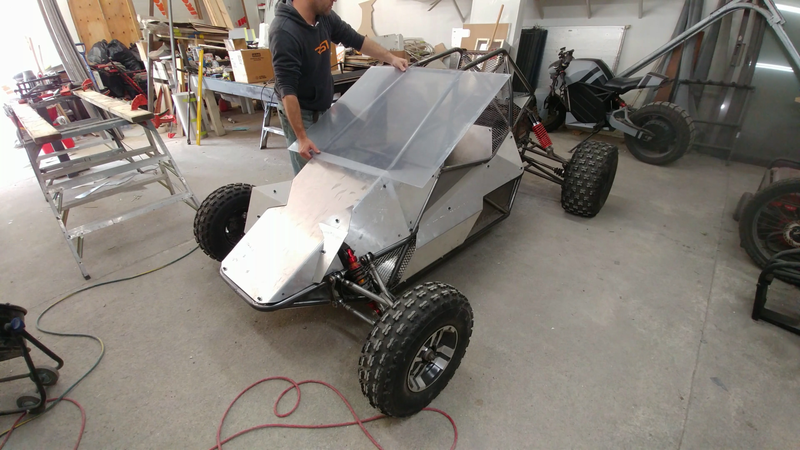
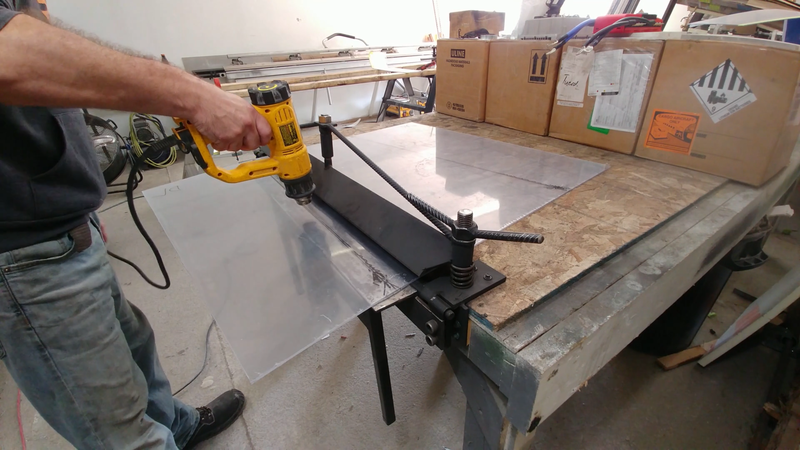
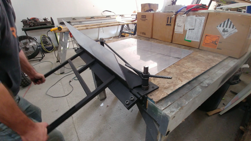
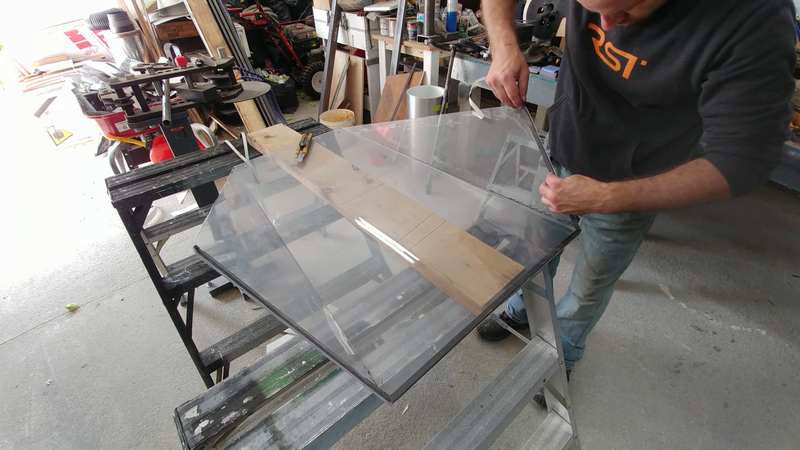
Next, I laid a sheet of 1/8" thick UV stabilized polycarbonate onto the chassis where the windshield will be located, and marked out the main tubes and hood so that I knew where to cut and bend the plastic for a tight fit. Once I had it marked out, I set it up in my sheet metal brake for the first bend. Before bending, I heated the polycarb along the bend line with a heat gun until it was more flexible (but not too soft), then clamped the piece and bent it. There's a fair amount of springback when bending polycarbonate, so I had to overbend quite a bit to get the angle that I needed. But it worked out fine. Once the angle was established, it held its form when the plastic cooled. I should have put tape over the brake clamp edges though, as they made a few scratches in the plastic.
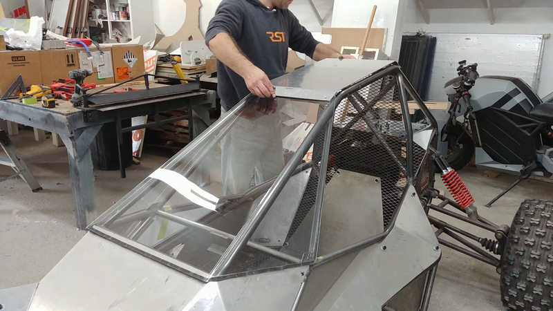
After adding some 1/4"x1/2" weatherstripping foam to the bottom inside edge of the windshield, all I had left to do then was bend the aluminum plate for the top of the chassis and then install it with the windshield. They're arranged so that the windshield overlaps the hood, and the top aluminum plate overlaps the windshield, so that they're all shedding water properly if I get caught in the rain or hit a big water hole in the trail. The BMS is going to be located under the dash, just behind the hood, so my main concern is keeping that area absolutely dry. The battery boxes will be made waterproof, so there's no worry in that regard. Speaking of which, building and fitting the battery will be the next task starting tomorrow. I'm not going to wire anything up yet, I just want to fit the cell packs in the cabin to make sure everything fits properly and I don't have to make any modifications before it's all painted. I'll have another video covering that in a couple of weeks. Make sure you've subscribed on Youtube and click the notification bell so you don't miss it.
|
AuthorJames Biggar Archives
March 2023
Categories |


 RSS Feed