|
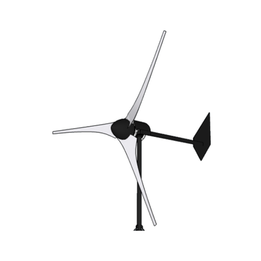
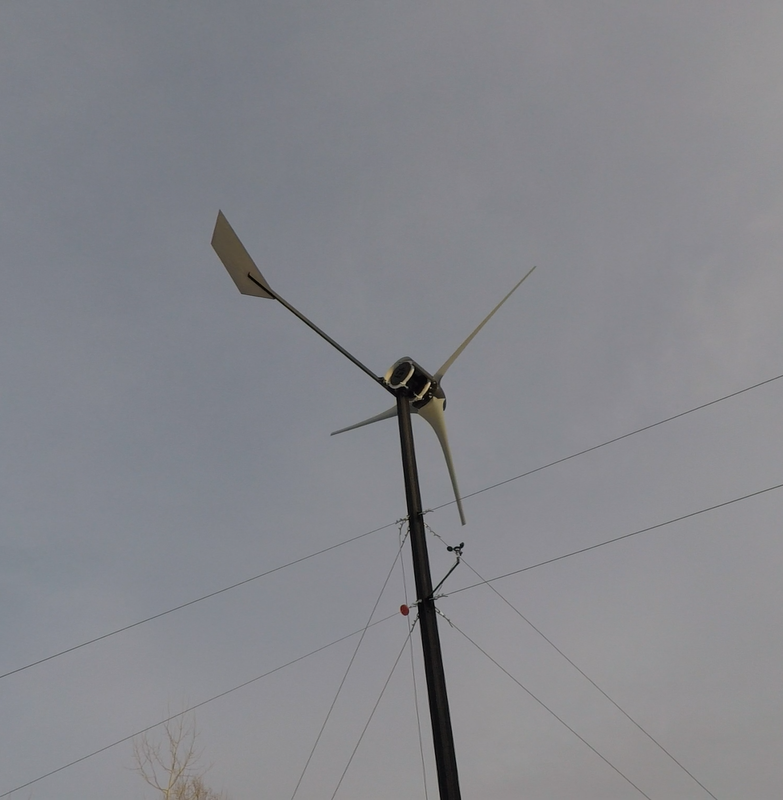
In this video I build an axial flux wind turbine with a 12 ft (3.7 m) diameter rotor driving two 12 coil/16 pole axial flux permanent magnet generators that produce up to 3 kW in a ~30 mph wind stream. In an area with a mean annual wind speed of 11 mph (5 mps) or higher, this turbine will produce 500 kWh+ of energy every month, nearly enough to take an avg home completely off the grid.
Specs:
Rotor diameter: 12ft (3.7m) Swept area: 113sq.ft (10.5sq.m) Blades: 3 @ 72", SD7032 airfoil TSR: 7 Generator: direct drive, dual rotor PMG Power: ~3 kW @ 30 mph (13.4 mps) Voltage: 12, 24, 48 VDC Cut-in speed: 5 mph (2mps) Overspeed protection: furling tail mechanism Monthly production: 500 kWh @ 11 mph (5 mps) mean wind speed
Axial flux HAWTs are among the most efficient wind turbines in use today, and the
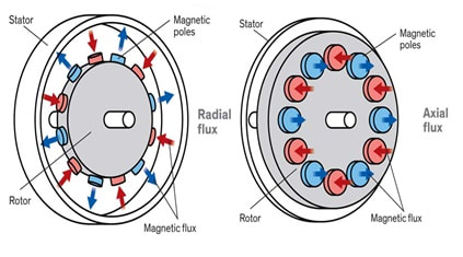
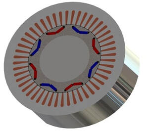
key to their well known reliability lies in the stator, or what isn’t in the stator to be more accurate. Before I get into the build details, I think it would be best to explain more about the axial flux configuration and why I'm using it. Most wind turbine generators are of the radial design, which means that the flux produced by the magnets flows perpendicular from the rotor shaft through the coils and back. The stator coils are wound around laminated steel cores which attract the flux and helps direct it across a long air gap through the coils and back to the rotor magnets again. The downside with this configuration is that the magnets mounted on the rotor shaft are naturally attracted to the steel stator coil cores, so as each magnet passes a coil, a ‘tugging’ or pulsating resistance against the rotor is created by the attraction between the magnet and the steel, commonly called ‘cogging’. Cogging has a negative effect on both start up speed and overall efficiency because it requires more wind power to overcome the resistance.
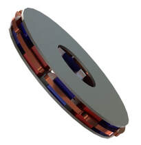
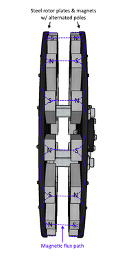
An axial flux generator is configured so that the magnet flux runs parallel to the rotor
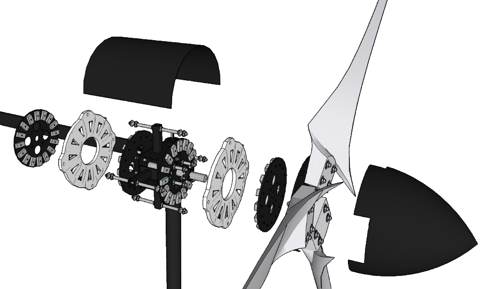
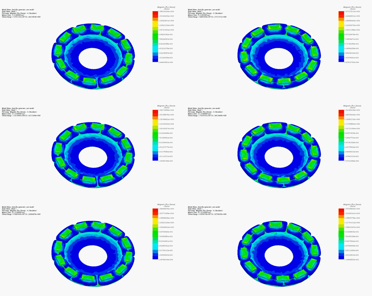
shaft. The stator is commonly referred to as an ‘air core’ stator because it contains no steel to cause the cogging effect. Instead of wrapping the coils around a steel core to direct the flux, the axial flux coils are encased in resin and the subsequent stator is mounted between to large, round steel rotor plates to which the magnets are attached on the inside faces. The steel plates move in unison and direct the magnet flux from one plate, across a much thinner air gap through the coils to the other plate and back without causing any resistance on the rotor. An axial flux generator will also have a high # of active windings and less overhang which means the coil turn count can be increased without increasing heat caused by the end effect. The other advantage to the axial flux design is that anyone motivated and with access to basic hand and power tools can build it - no expensive professional machining equipment needed!
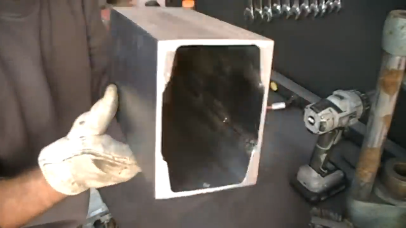
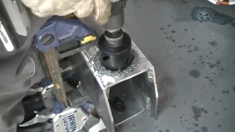
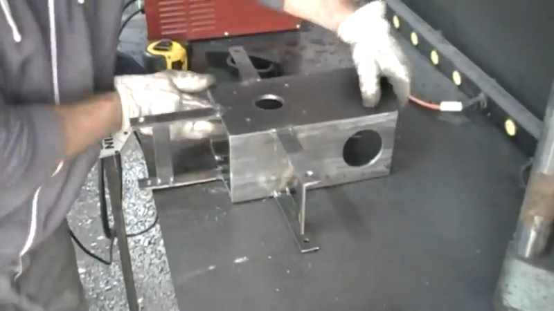
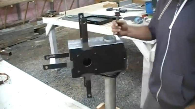
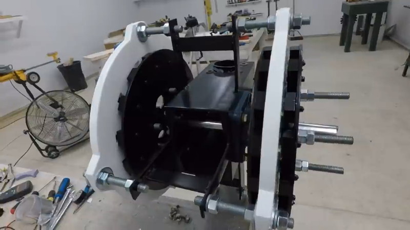
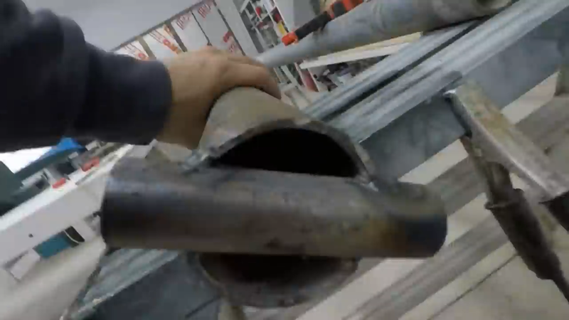
I began the turbine build by making the steel frame, specifically what's sometimes called the 'torque tube', which is the portion that the flange bearings for the rotor shaft mount to. I used scraps that I had laying around in the workshop, which resulted in using some heavy 4" A36 channel and 3/16" thick steel plate to form a 4"x6" rectangular tube - a standard rectangular tube would be a bit lighter and save a lot of work. I drilled a 3" hole through the 4" faces on one end of the tube to receive the yaw pipe, which is the top portion of the tower that the turbine will swivel on to track the wind. I then drilled an 1-1/2" hole through the 6" faces on the opposite end for the rotor shaft, approx. 6" center to center from the first set of holes. Then I drilled out the mounting bolt holes for the flange bearings, and cut a half dozen pieces of 1/8"x1" steel flat bar and welded them to the tubing to serve as the stator mounts.
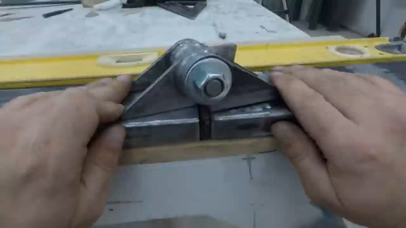
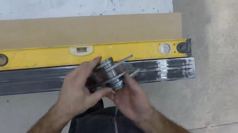
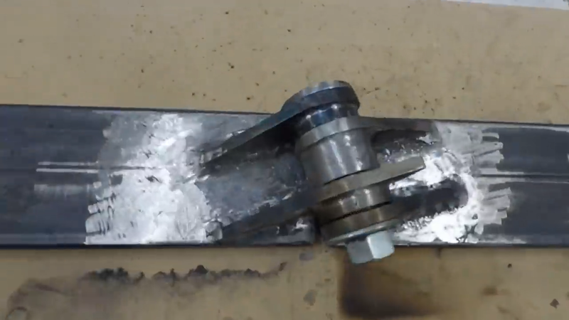
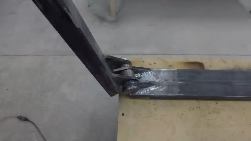
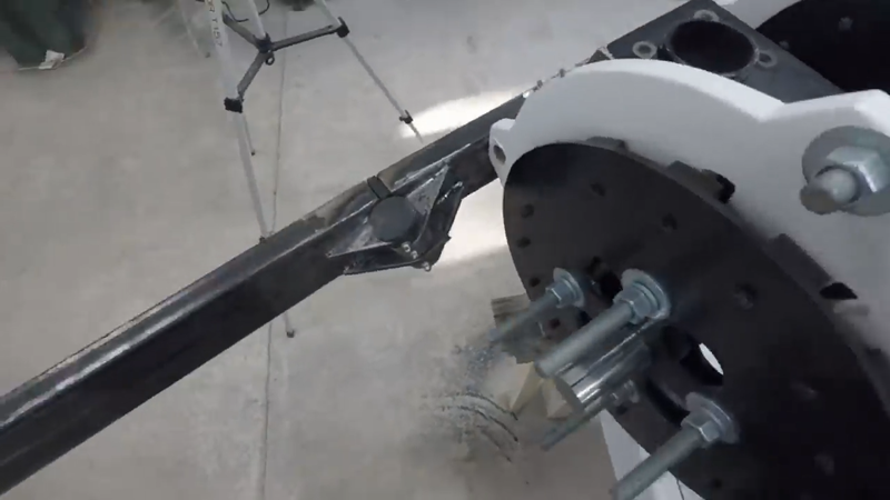
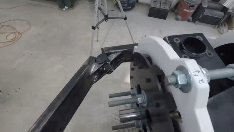
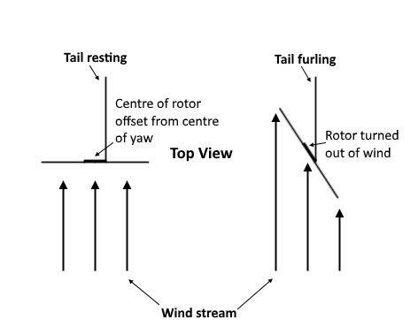
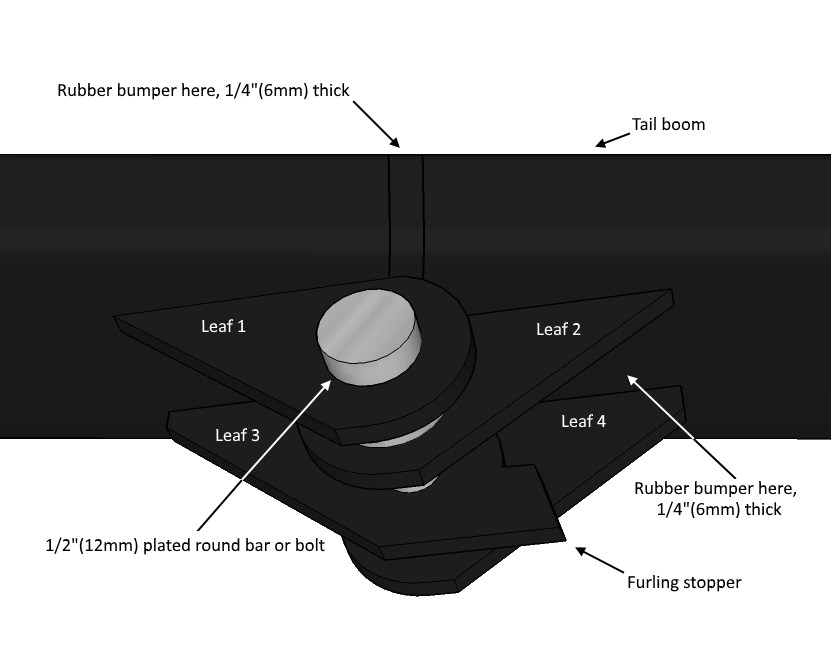
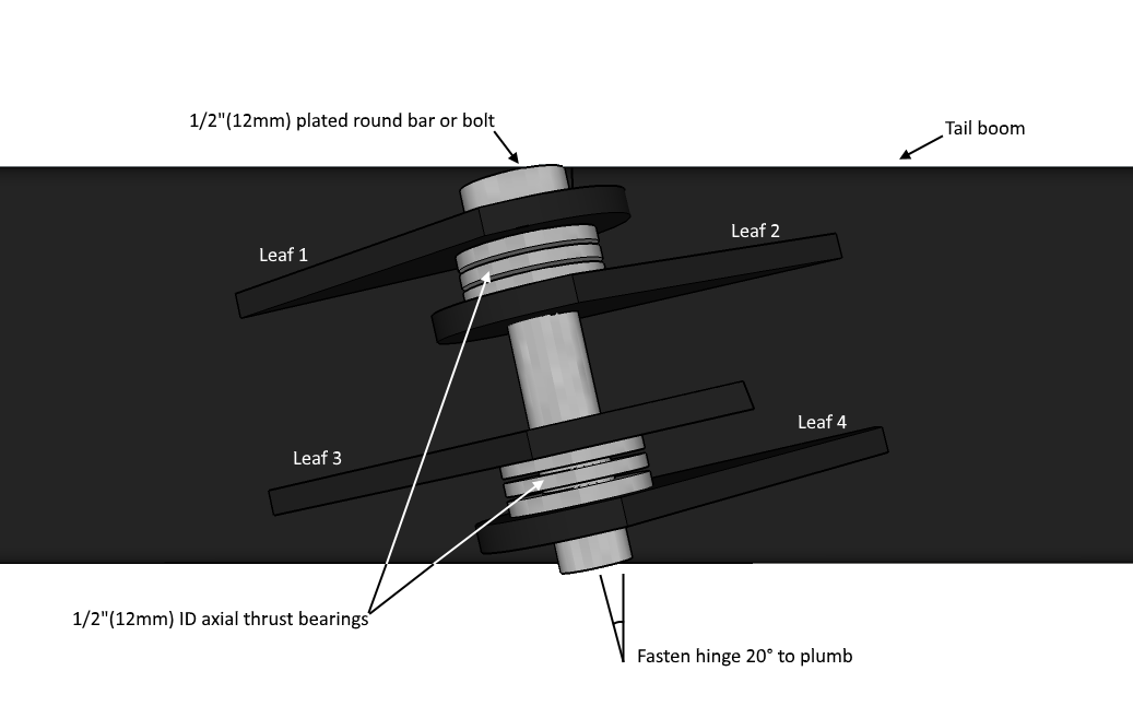
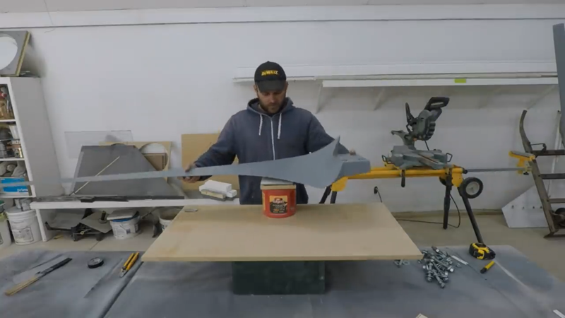
You're probably wondering why the rotor shaft is offset from the yaw. This is to accommodate the furling mechanism, which will be the mechanical automatic overspeed control for the rotor in the form of a furling tail, or 'wagging' tail as I call it because the tail boom looks like it's wagging like a dog's tail when it's operating. This happens by way of the rotor offset from the yaw and a special compound angled hinge that connects the 1"x3" tail boom to the frame, shown below.
When the wind speed reaches a certain level, the rotor being off-centered from the yaw will cause it to turn out of the wind so that the amount of swept area facing it is minimized and in turn limit (but not shut off) power output to a safe level by limiting the rpm of the blades. The angled furling tail hinge will allow the tail to remain tracking the wind but lifts it in the air during the furling process. With the rotor turned out of the wind, there's less force pushing the blades so they won't exceed a safe operating rpm. As the wind speed decreases to a safer level, gravity overcomes the wind and lowers the tail but remains tracking while the hinge forces the rotor back into the wind to optimize production again. The moment the tail lifts is what's called the furling moment, and getting it to happen at the right wind speed requires a certain offset, hinge angles, tail length, vane size, weight, etc. These are all detailed in the plans for this project.
I made the furling hinge a bit more complicated than it needed to be; the bearings can be replaced with a few 1/8" thick flat bronze washers set between the leaves. Simple and cheap. One of the leaves has a stub on the end that serves as a stopper for the tail to keep it from swinging too far. I also fastened a piece of rubber form an old tire in the joint behind the hinge to keep the tail boom from smashing into metal every time it swings. Once the hinge was made and the tail boom was installed, I tested the swing to make sure the tail vane wasn't going to hit the blades when they're installed later.
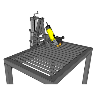
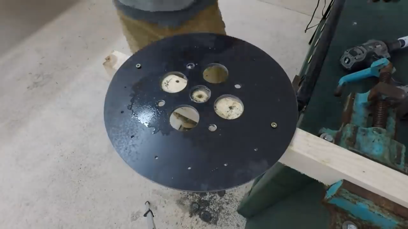
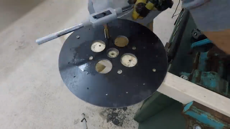
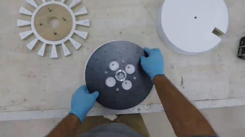
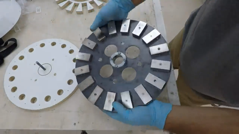
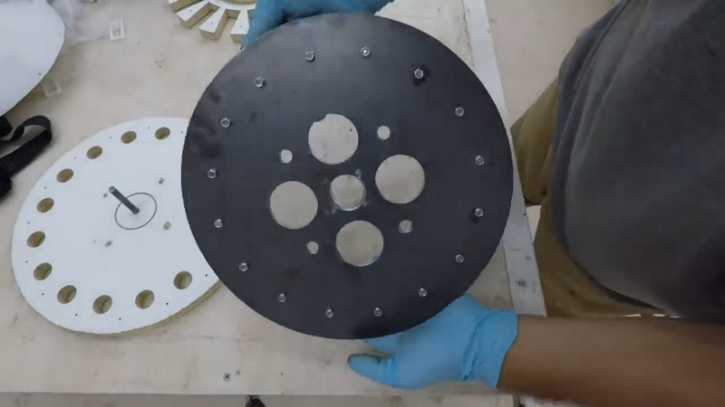
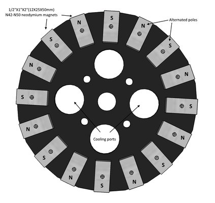
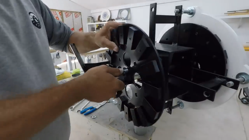
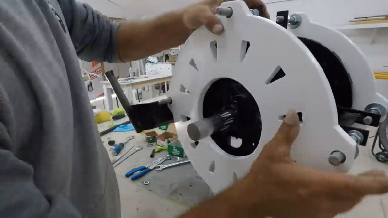
Next, I tackled the generator. I used my DIY modular tool guide to cut the magnet rotors and blade hub from 1/4" thick steel plate with an angle grinder. With the angle grinder on the guide, I can cut perfect circles of almost any size without needing a lathe or CNC. Once the plates were cut, I drilled out the mounting bolt holes for the 1x2x1/2" N45 neodymium magnets, as well as threaded the mounting/jacking bolt holes for the rotors themselves, and some large cooling ports to help the generator shed heat better when it's working in high winds.
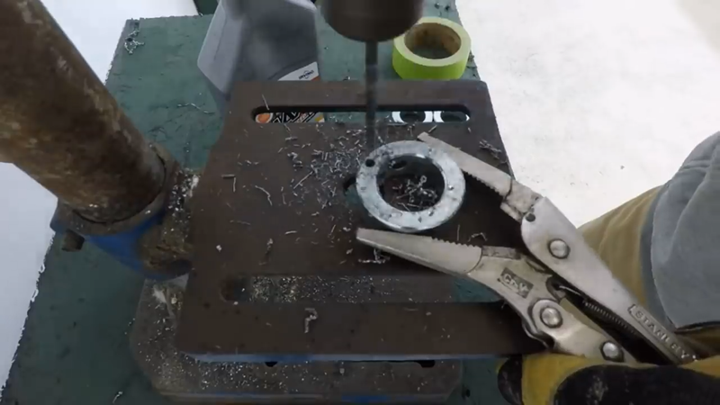
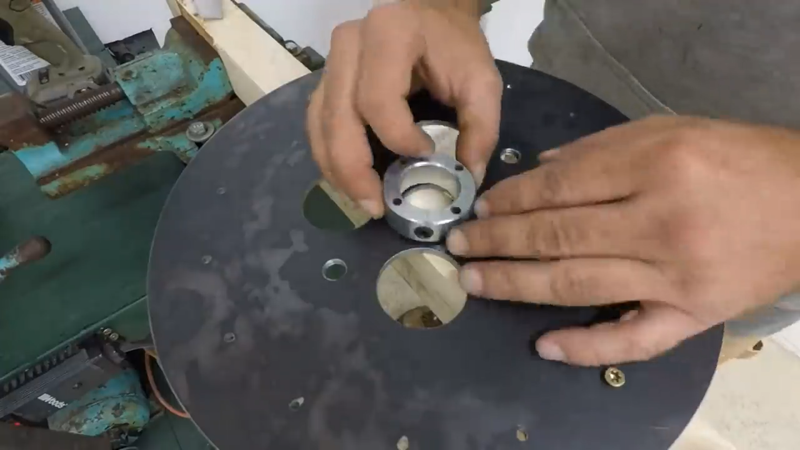
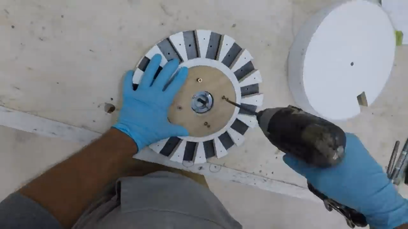
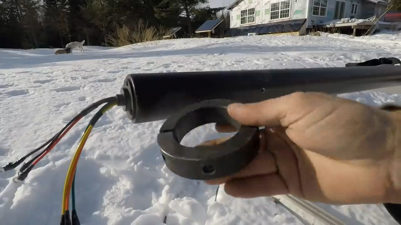
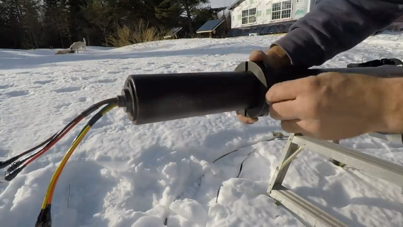
I drilled and bolted a 1-1/4" shaft collar to each plate to serve as a hub for connecting them to the rotor shaft with set screws.
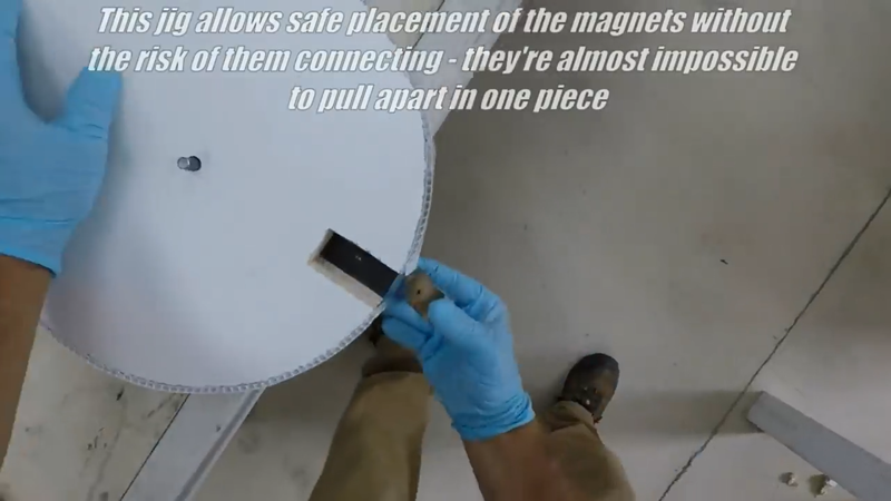
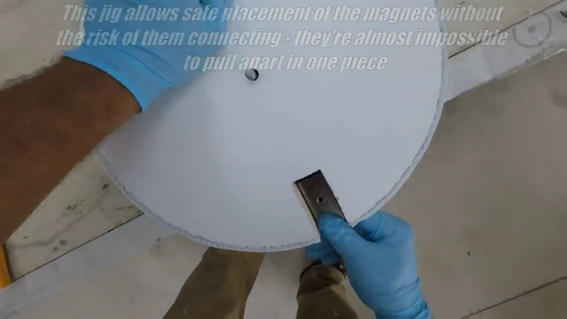
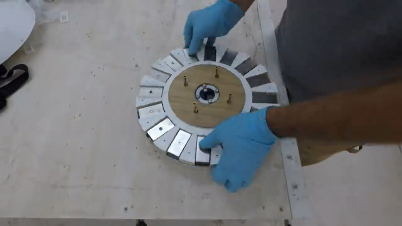
Then I installed the 1"x2"x1/2" neodymium magnets using JB weld, #8 machine screws & lock nuts, and a wooden jig that I made to hold the magnets in place as I'm securing them - they're extremely strong (~80 lbs of pulling strength each) so I had to be careful not to get them too close to each other or get my hands or fingers pinched. That pulling power also means that if the rotor plates are placed too close together before they're mounted to the shaft properly, then separating them will be like trying to lift a pickup truck. You don't want a hand or finger getting caught between them if that happens, because you'll probably lose it.
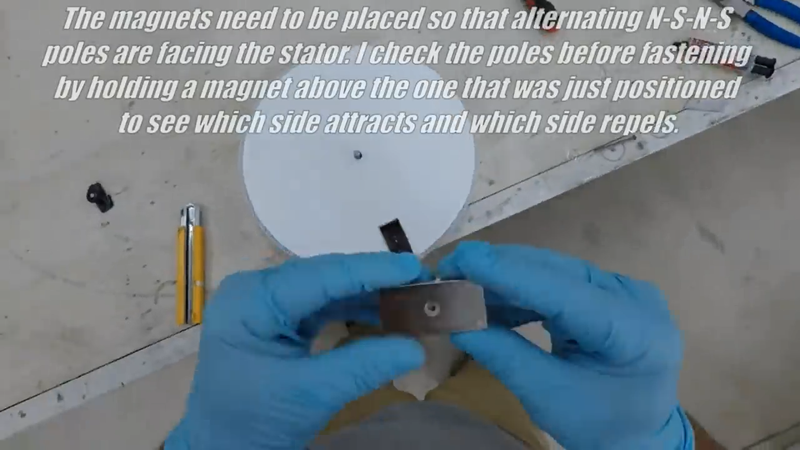
To carry the flux across the air gap between each rotor plate when the generator is assembled, the magnet pole faces need to be alternated on each plate. Opposites attract when it comes to magnetism, so all I had to do was fasten one magnet in place, then carefully held another magnet tightly in my hand and hovered it over the first magnet to see which faces were attracted to each other, then placed the next magnet with the opposite pole (attracting face) face up on the plate, and so on with all of the remaining magnets. Once one plate was covered in magnets, I started the second plate (for the first generator) with the opposite pole face up compared to the first magnet on the first plate. This is because the poles facing each other on each plate need to be alternated when they're installed onto the rotor shaft too, as shown below.
After the first pair of plates were finished, I made another pair to match then cleaned them all with rubbing alcohol and primed and painted them, then set them in a safe place FAR from each other until they were ready to install.
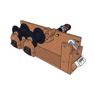
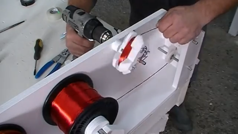
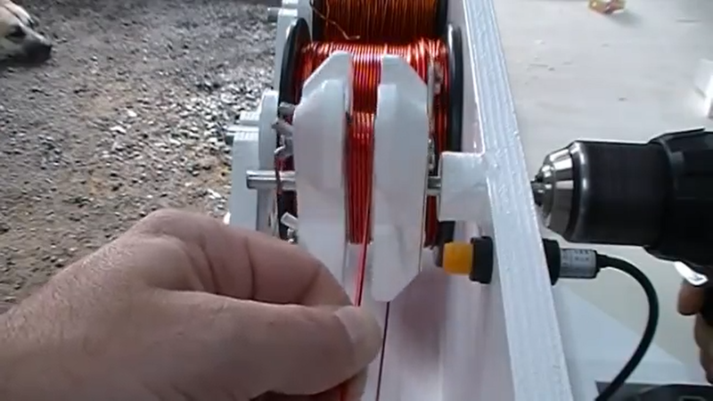
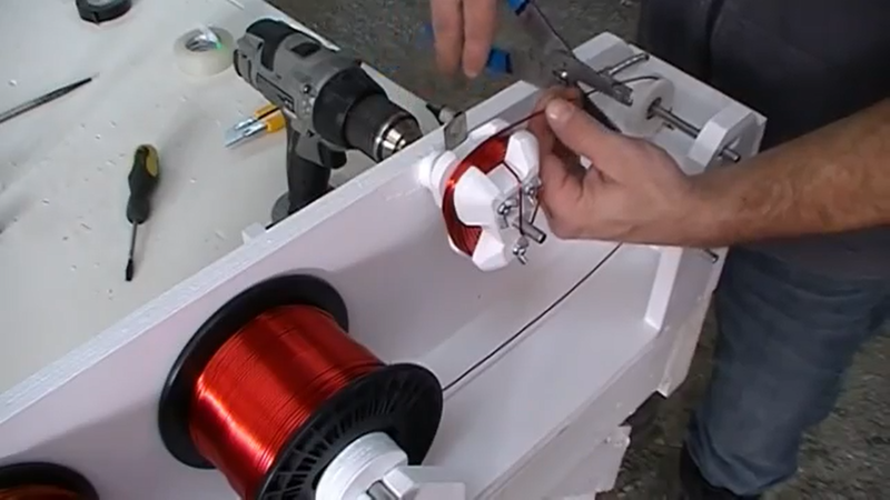
Next, I got started on winding some coils. I used my DIY drill operated coil winder to do the job. A certain winding turn count is required for different system voltages so that a turbine will cut-in (ie begin charging) at a reasonable speed. For this particular turbine, to get a 5 mph cut-in speed with a 12V system a person will need to wind 40 turns of double parallel strand wire in each coil, for 24V they would need 80 turns of double parallel strand, and for 48V they would need 100 turns of single strand - all using 14 awg wire. Double parallel strand means winding two wires together at the same time, and connecting the ends so they act as one large wire. This is needed for the lower voltage systems because they will need to carry more current (amps) in order to generate the same power as higher voltage systems (watts = volts * amps).
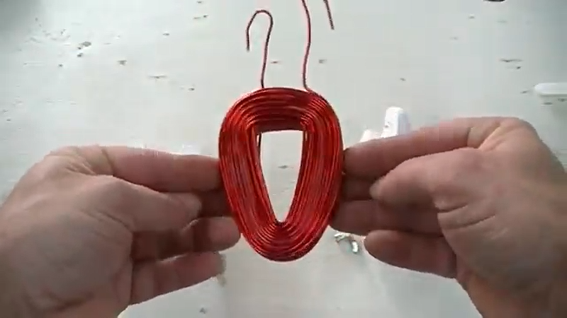
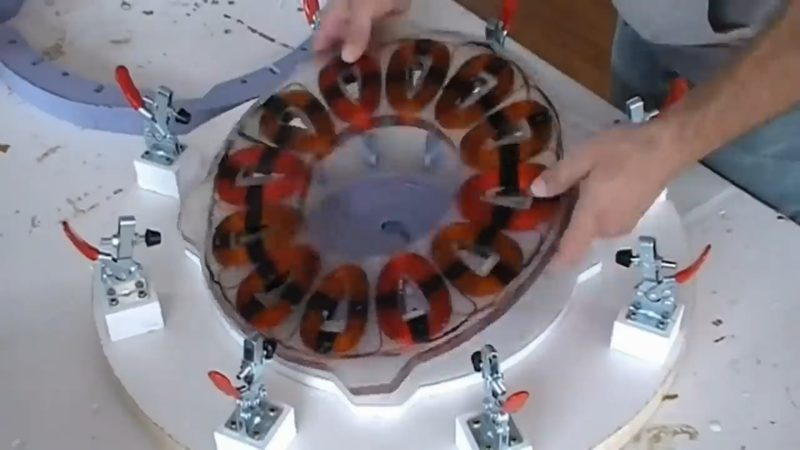
Ideally, the inside perimeter/shape of the coil should be the same as the magnets being used, but some compromise for the sake of space won't have much affect on performance. I wanted to minimize the footprint of the generator, so I chose the wedge shaped coils instead of rectangular coils so that I could fit them into a tighter radius. The outer edge and length of the inside profile of the coil is still the same as the magnet dimensions, the inside edge is just narrowed. When building a custom turbine for the first time, it's a good idea to wind a couple of coils before building the mag rotor plates, and lay them out on a flat surface as they would be in the stator to test how they would fit in relation to the magnets on the rotors; the magnets need to line up with the center of the coils to limit flux loss.
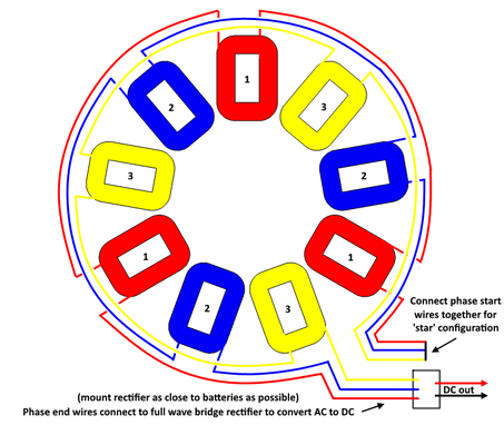
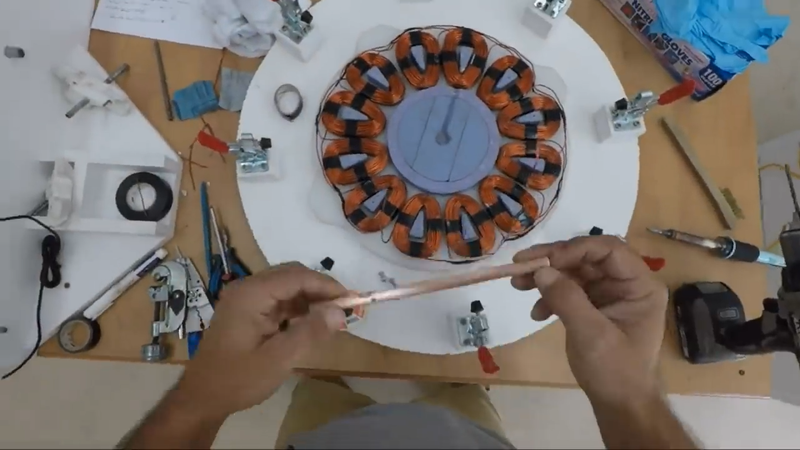
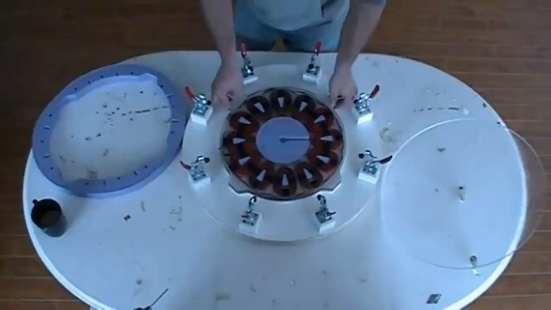
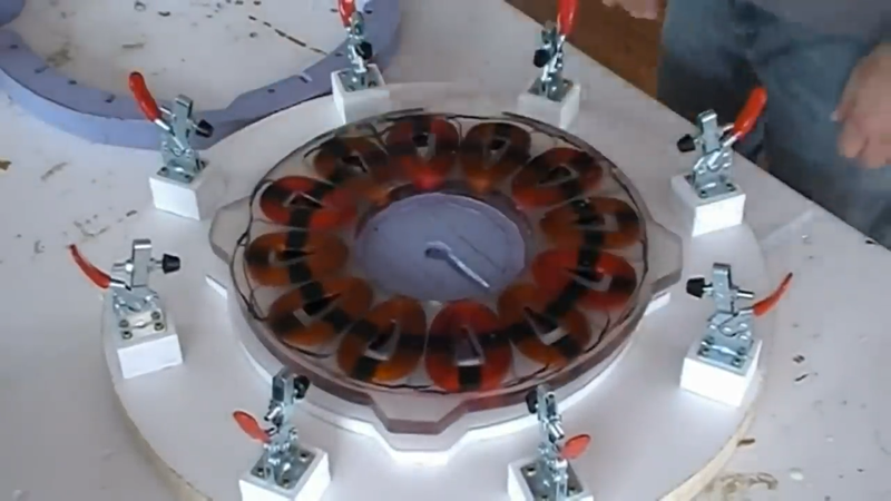
After I wound all the coils and taped them up with electrical tape to keep them as tight as possible, I soldered them together in a 3 phase star configuration as shown below.
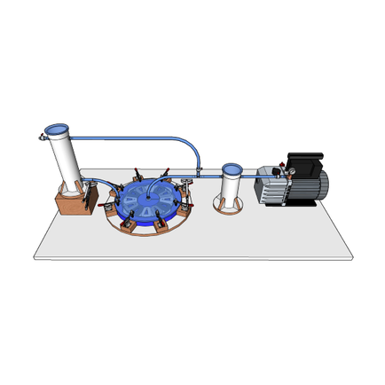
I then checked the continuity of each phase with a multimeter set to 'ohms' to make sure the connections were fine, resistance was low and that current would flow. Then I taped all of the loose wires and coils together, and prepped my DIY vacuum injection mold for casting the stator.
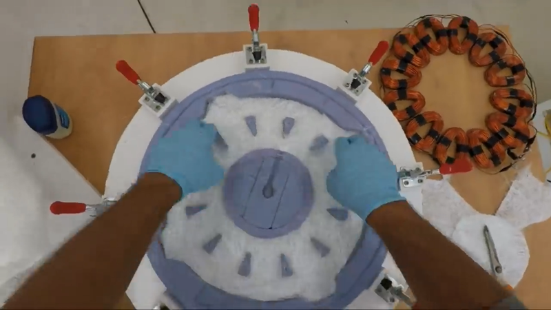
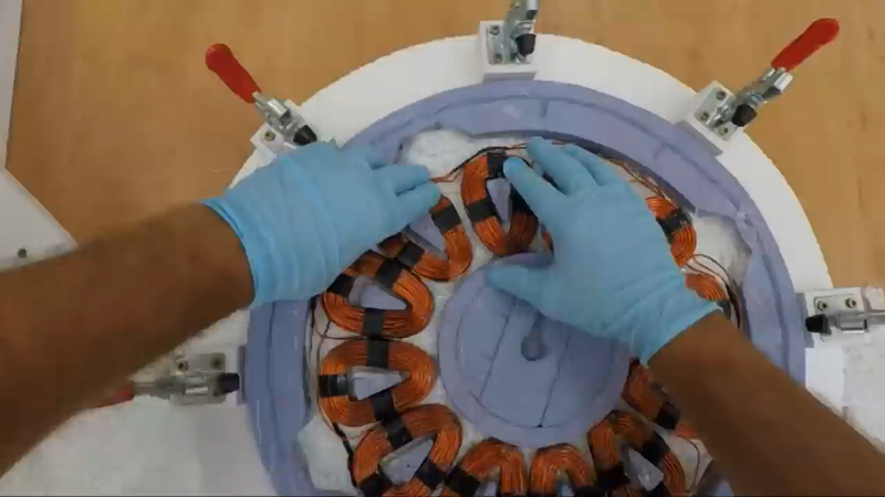
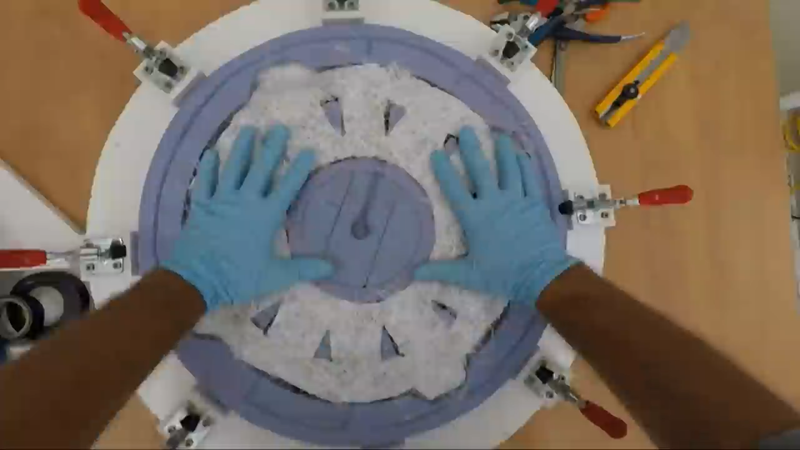
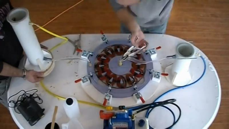
I applied a layer of petroleum jelly on all of the mold surfaces, then cut two pieces of fiberglass mat to place on the top and bottom of the coils when casting to add reinforcement to the stators. I used casting epoxy to cast these stators, but I prefer using UV stabilized polyester resin because it cures faster. After both stators were cured, I gave them a quick sanding and then primed and painted them. Vacuum injection isn't necessary for this, though. A person can make a simple wooden mold for the stator and pour the resin by hand. A few air bubbles are likely to get trapped in the cast, but they'll have no effect on performance or longevity.
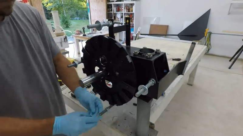
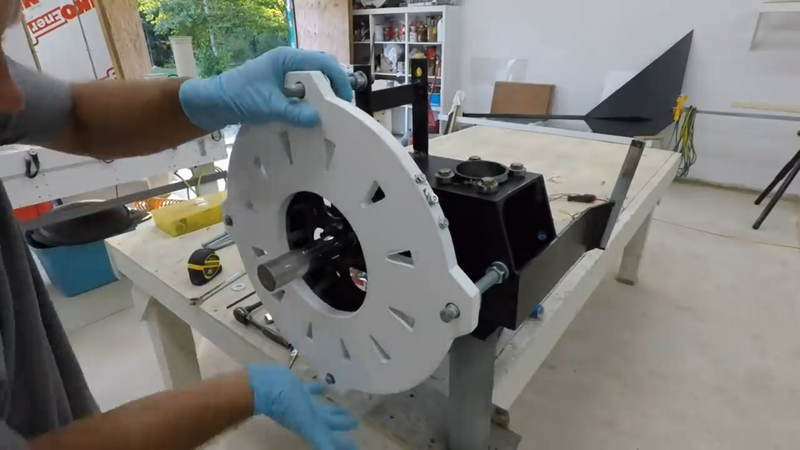
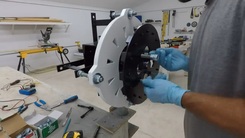
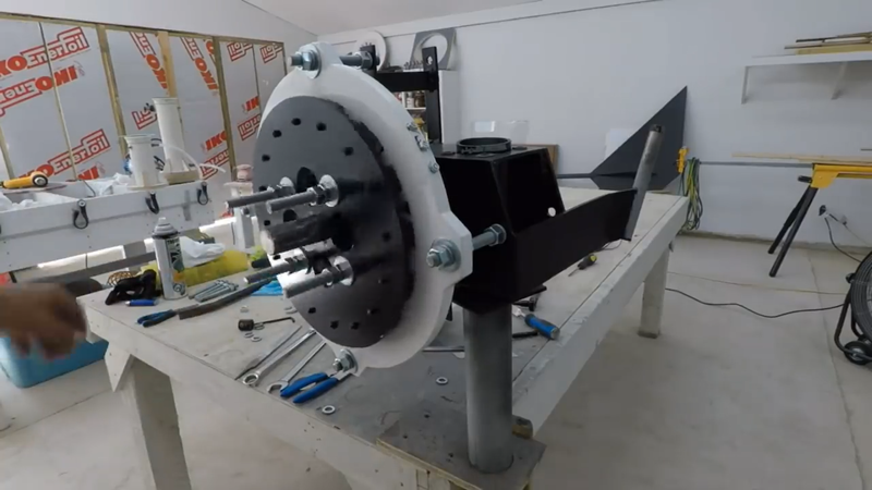
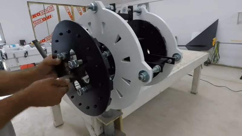
The next task was to assemble the generator. This is the nerve wracking part because the magnet rotor plates need to be jacked together without pinching fingers. I started by installing the inside rotor plate onto the front of the rotor shaft, then threaded the stator bolts onto the stator mounts and installed the stator. I used nuts and washers behind the stator to adjust it as close to the inside rotor as possible without them rubbing together. Because the magnetic flux needs to travel from plate to plate, the closer they're together the more flux that can be focused into the stator and the more power it will produce. The 'air gap' between the rotors should be as thin as possible.
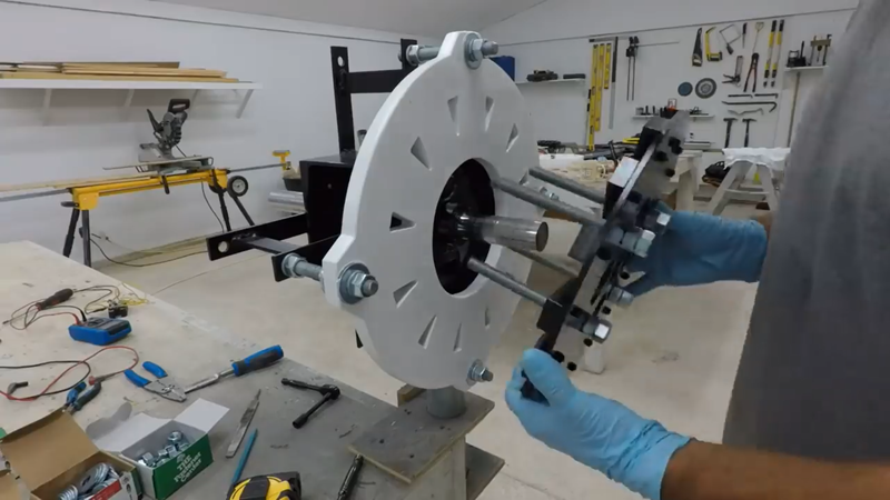
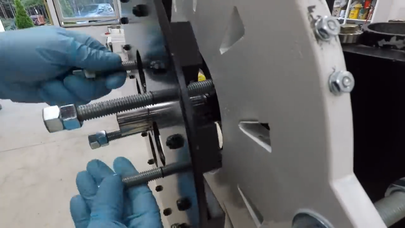
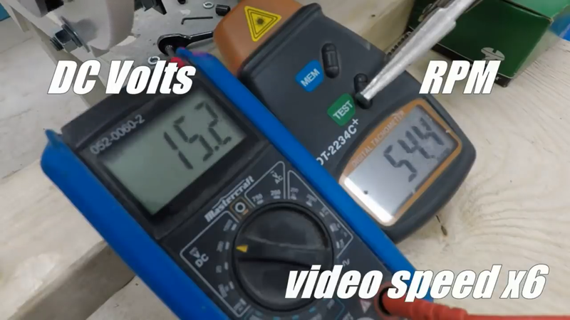
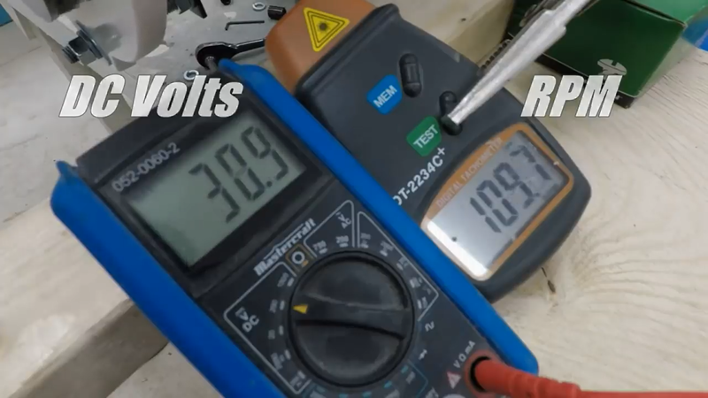
Once the stator was set, I installed 6" long jacking bolts into the threaded holes in the second rotor plate with the majority of the bolts' length protruding on the inner side of the rotor plate to keep it as far as possible from the generator assembly when I start jacking them together to close the air gap. Two hex nuts locked together on one end of the rods will serve as heads, like on a bolt. I placed the protruding ends of the roads against the inside rotor plate that was previously mounted on the shaft, making sure that I have the poles lined up properly, and then started slowly jacking the outer plate toward the stator by turning each rod a few turns at a time until the outer rotor plate was within ~1/8" of the same distance from the stator as the inner rotor plate. Then I lined the jacking bolts up with the threaded bolt holes in the inside rotor plate and threaded the jacking bolts into them, then locked them together with hex nuts and secured the rotor plates to the rotor shaft with set screws in the collars. Rinse repeat for the PMG on the back side of the turbine. After both PMG's were assembled, I connected each to their own 3 phase full wave bridge rectifier, and then connected the DC output from the rectifiers in parallel and checked the voltage output/rpm of the generators with a multimeter and digital tachometer to verify they'll cut-in at the speed that I want.
The generator assembly went well, so I immediately moved on to carving a set of blades from laminated spruce.
Most micro turbine blades are made of either solid fiberglass, fiberglass w/ a foam core, plastic, or metal. Industrial turbines use a combination of fiberglass and wood. This is my preferred method, as well, but using more wood and less fiberglass. A solid fiberglass blade is easy to manufacture, but they're a bit too rigid which lowers efficiency. Plastic blades are easy to manufacture and easier to recycle, but they don't last as long as fiberglass (ie, reinforced plastic). Fiberglass w/ a foam core decreases the amount of fiberglass needed and helps make the blade semi-flexible, which would be more efficient than a rigid blade. But separating the fiberglass from the foam core to recycle either or both without involving chemicals can be a bit of a problem. Steel is strong and flexible, but is heavy and decreases the rotor's response time and efficiency as a result. Aluminum is light and strong but too rigid. It won't flex like steel without bending permanently and cracking or worse, which also decreases efficiency compared to semi-flexible blades. The best method for micro wind turbine blades, imho, is the same method that small aircraft propeller manufacturers like Culver Props still use today, which is a carved wooden blade with a few layers of fiberglass cloth covering them for protection and added reinforcement. This is a time proven method that makes blades that will last decades, using minimal plastic components and a renewable, abundant and readily available natural material that is much easier to recycle and repurpose after it's done its job. The only difference with my blades is that I use softwood to keep them as light and flexible as possible, where plane props deal with higher loads and are usually made of stiffer hardwoods as a result. All that's required to recycle them is a lathe duplicator to strip the fiberglass layers from the old blade to expose the wood. The wood can then be repurposed into a new blade if it's still structurally sound, or it can be mulched up and composted while the fiberglass dust/debris can be mixed with polyester resin to make a polyester filler.
I don't just use any old stick of softwood, though. The lumber needs to have a relatively straight grain, no checks or wanes, and ideally it should have no knots for consistent strength and flexibility throughout the blade, but if knots are unavoidable then they should be small and secure in the wood. Questionable knots can be stabilized with resin before they're worked.
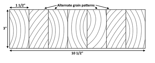
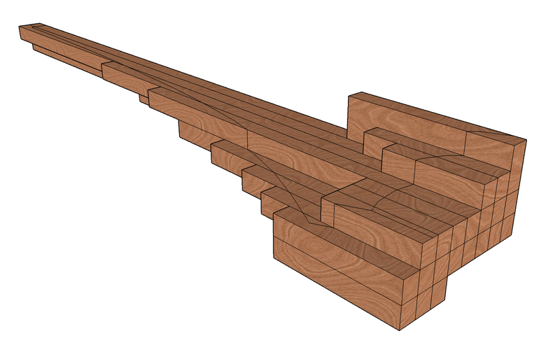
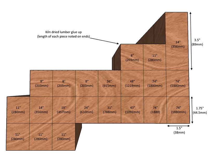
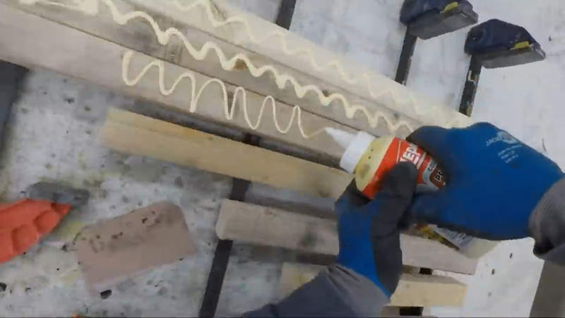
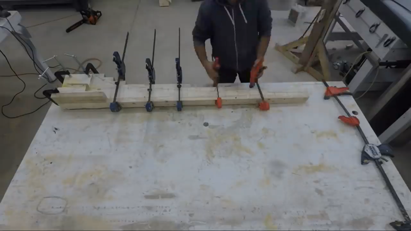
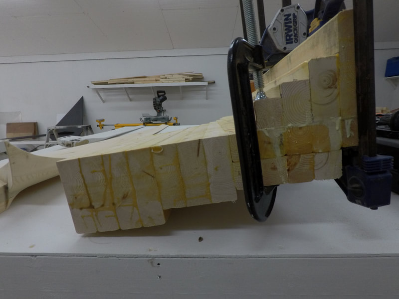
After I've chosen the wood that I want to use, I rip up the planks into narrow strips, usually 1-1/2" wide. Then I rearrange the strips so that the grain pattern is alternated in each piece and glue and clamp them back together into the blank that will be carved, like how a kitchen cutting board is made (see image above). This helps to even out any cupping or twisting that could otherwise happen if the grain was left in its natural state. This is important not only to maintain the angle of attack of the blade that will carved out of it, but also to keep the blades lined up on the rotor plane and balanced properly. It also helps to limit the waste from carving the blade because I can cut the narrow strips to almost exactly the length they need to be, as shown below.
After the glue had dried, I drew the outline of the blade profile onto the laminated block and cut it out with a circular saw and a reciprocator.
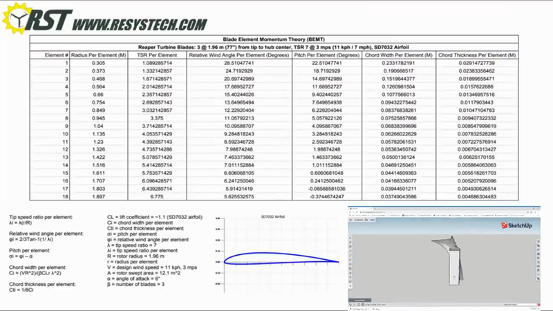
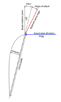
To make the blades perform as efficiently as possible, they need to be able to produce lift efficiently. This is done by using an airfoil and dividing the blade into different stations or elements along its length so that the blade's pitch, chord width and thickness can be adjusted according to the relative wind angle in that location in order to maintain the blade's angle of attack, and to optimize torque at the root section and speed at the tip. This design method is called blade element momentum theory. Of course, a person could hack away at a PVC pipe, bolt the pieces to a hub and watch it spin, but the result in power will be a fraction of what's possible with proper design. If you'd like to learn more about how to use BEMT to design your own blades from scratch, check out my turbine design guide.
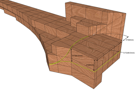
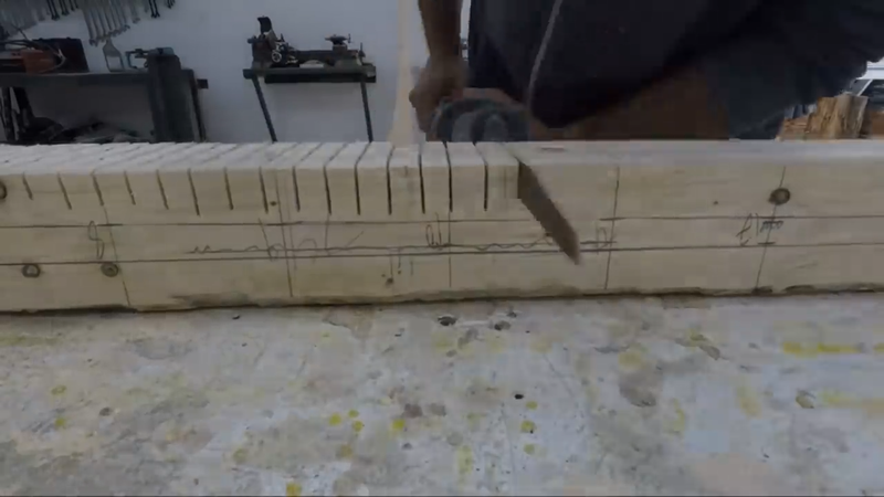
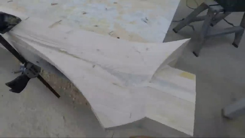
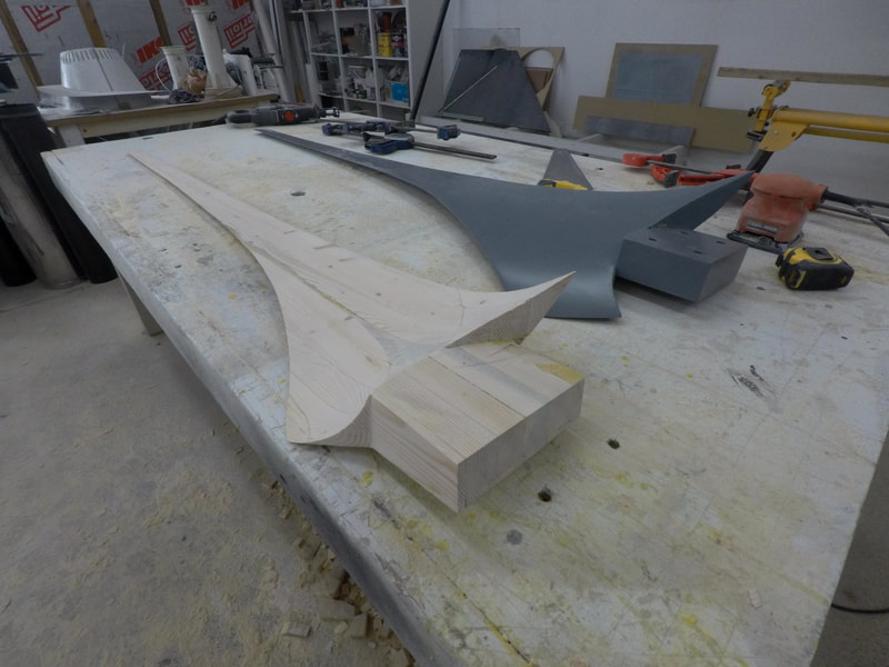
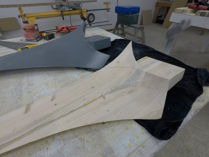
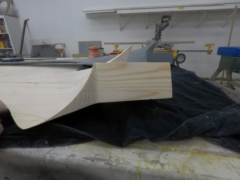
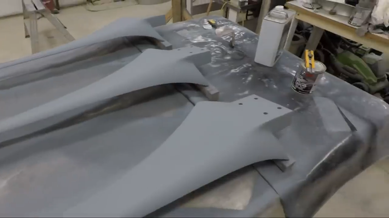
Once I had the blade's profile cut out, I used the data shown in the image gallery above that I had generated with my blade design worksheet, and laid out the stations along the blade and marked the drop for the trailing edge at the bottom edge of the laminated blank. The leading edge is represented by the top edge of the blank. The drop is the distance the trailing edge drops below the top surface of the blank, representing the front of the blade. You'll notice from the images below that the drop is different at each station. This is because the relative wind angle is different at each station, so the pitch of the blade will be different at each station to compensate, which results in a twist in the blade called a washout.
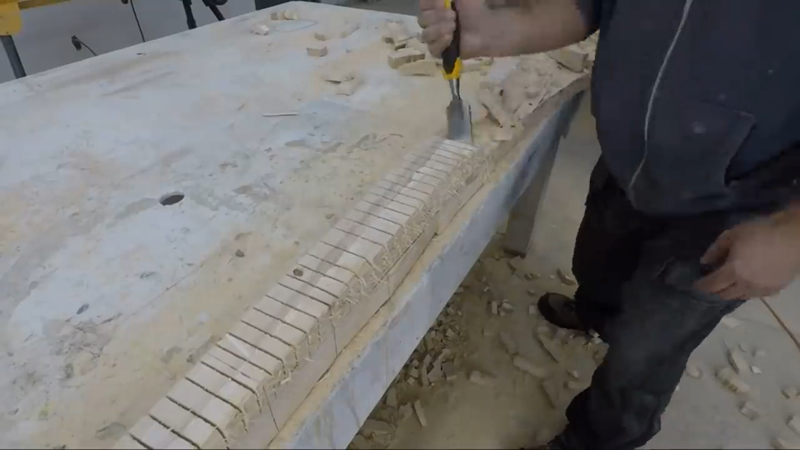
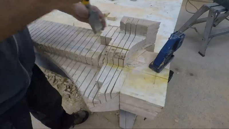
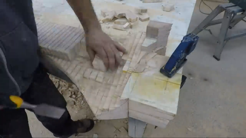
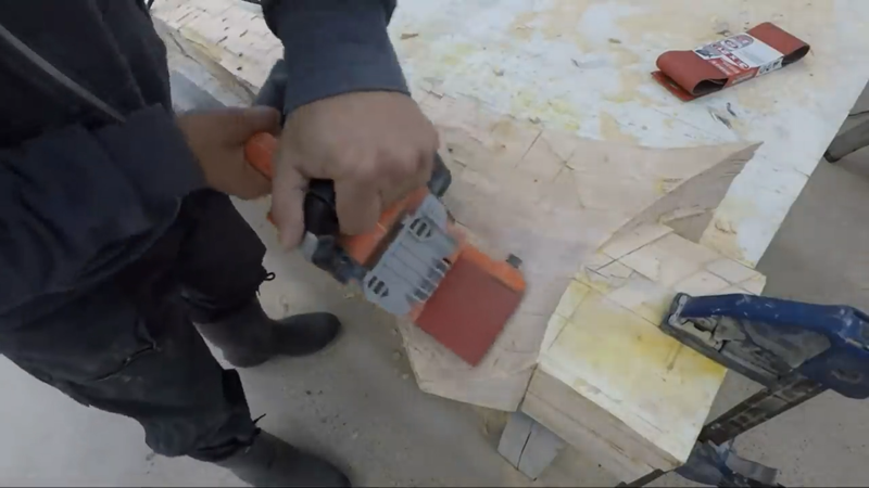
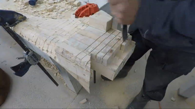
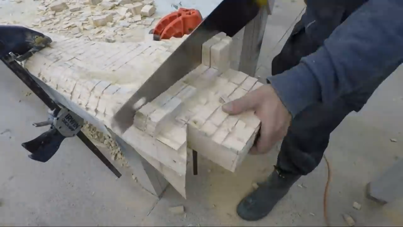
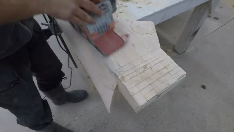
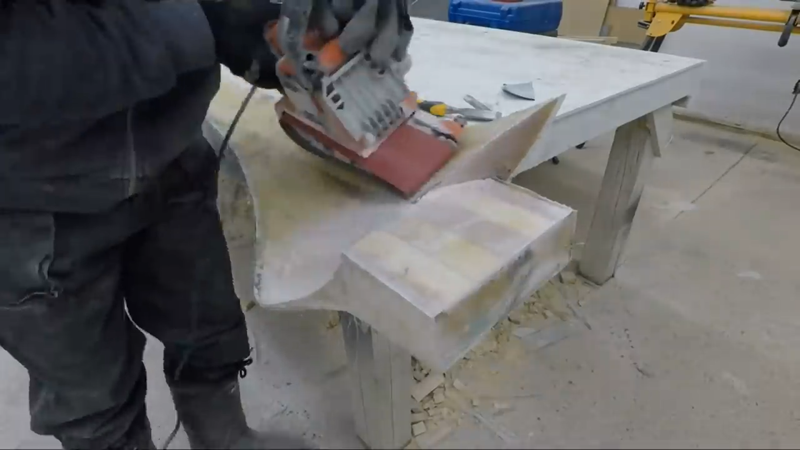
With the stations and trailing edge laid out, I began making a series of cuts along the blade approx. 1" apart, down to the drop marked on the trailing edge and connecting with the top of the leading edge. Then I used a hammer and chisel to break out the pieces and expose the blades new front face, and then sanded it smooth with a belt sander.
I repeated the same process on the back side of the blade, except the drop on the trailing edge had to connect with a line that I drew approx. 2/3 of the distance from the trailing edge to the leading edge, which represents the thickest portion of the airfoil. Then I rounded over the leading edge to finish the airfoil profile.
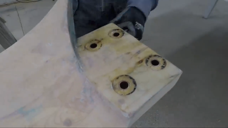
You'll probably notice that the back of the blade where it connects to the hub is angled a bit (approx. 4°). This will angle the blade tip 4° away from the tower to allow some room for flexing in high winds. Most builders and manufacturers will either keep the rotor plane perfectly vertical or angle the generator with the rotor ~4°, depending on the type of blades they're using (rigid or flexible). But I've found the easiest method is to just angle the blades on the hub and keep everything else level and plumb.
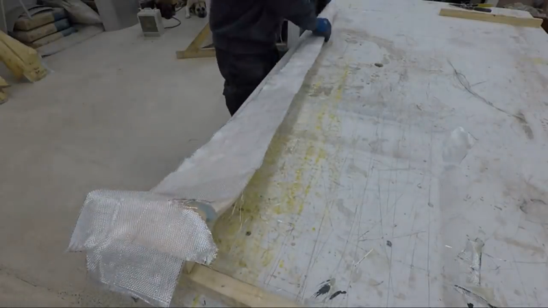
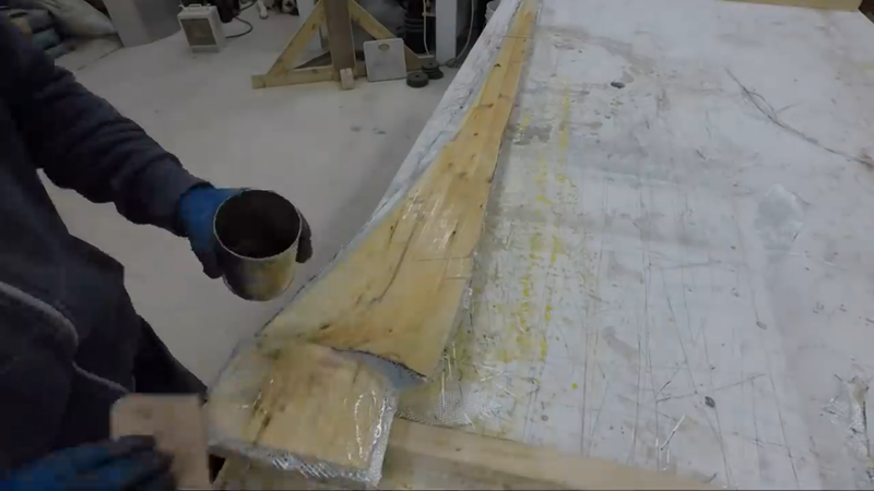
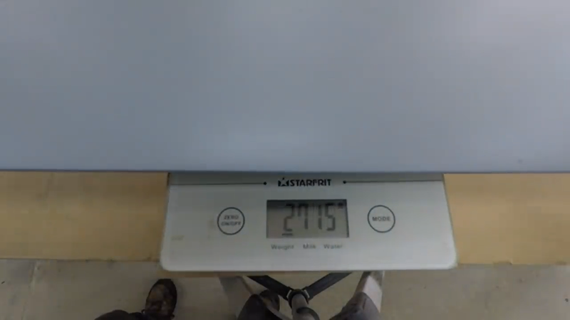
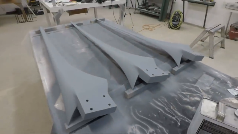
After each blade was sanded, I cut some 10 oz fiberglass cloth and mixed up some polyester resin and put 3 layers of cloth on both sides of each blade. After the resin cured, I trimmed off the waste with an angle grinder, then drilled 4 holes for mounting bolts in each blade. To protect the wood, I epoxied bronze bushings in the holes. Then I sanded the blades smooth, weighed them, and removed more material where necessary so that they were almost exactly the same. When I was satisfied, I finished them with a few coats of paint.
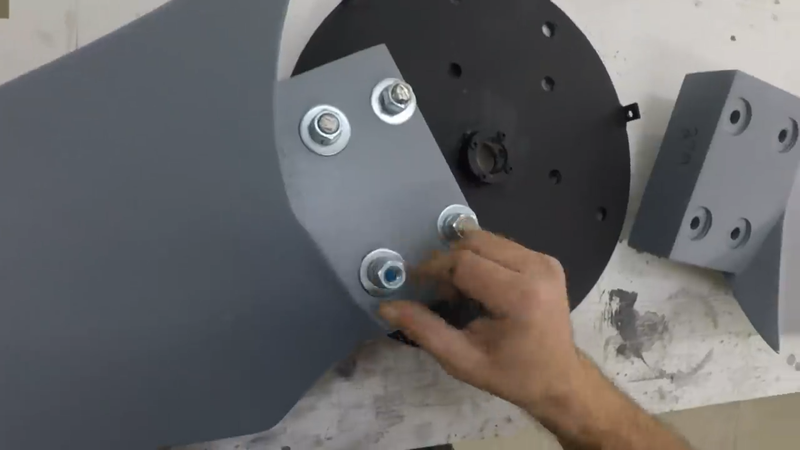
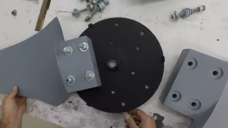
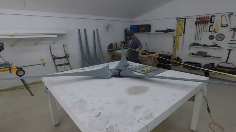
Next, I attached the blades to the blade hub. To help with balancing, I measured the tip to tip distance between each blade. With the bolts just hand tight, I adjusted the blades where necessary to space them apart equally, then tightened the bolts permanently.
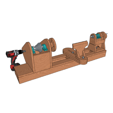
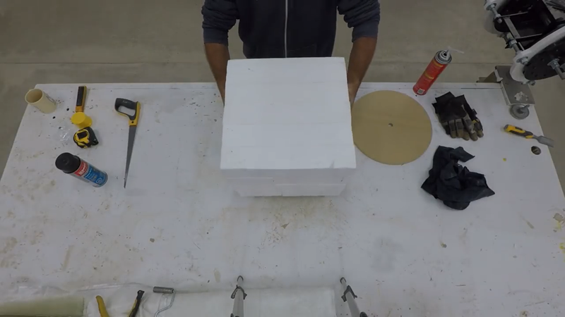
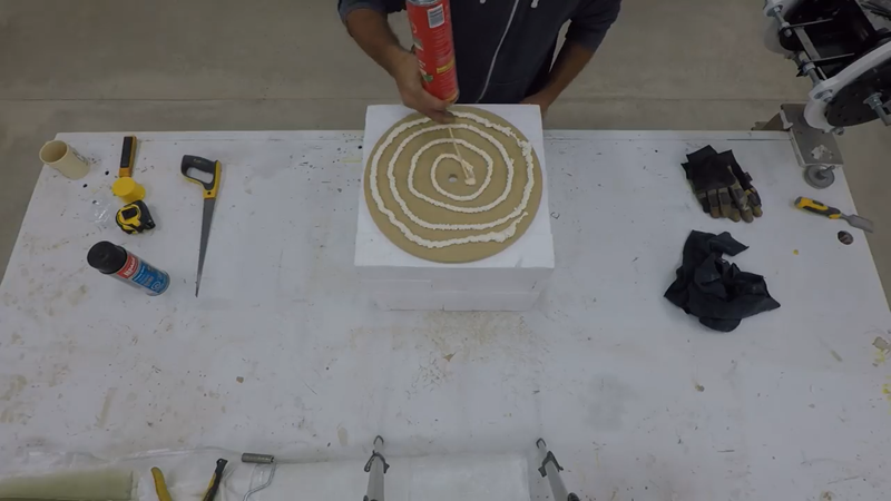
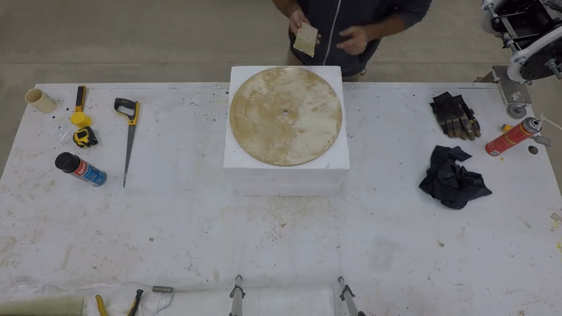
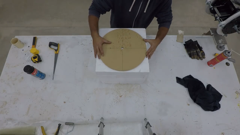
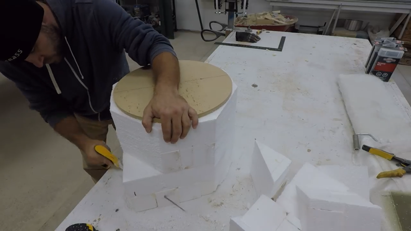
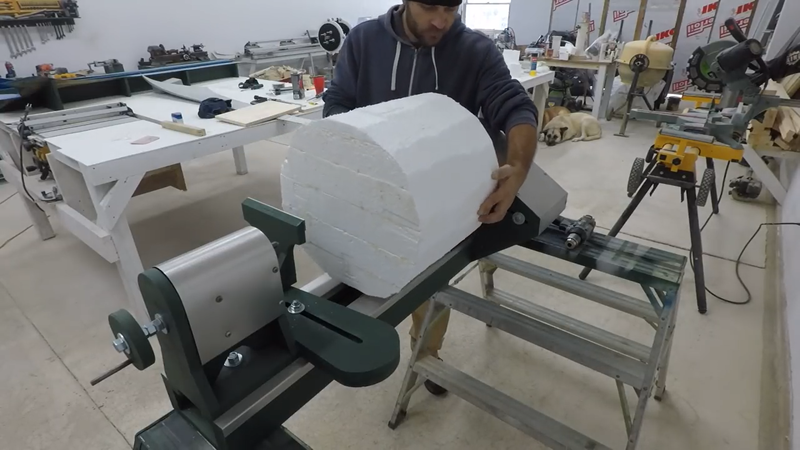
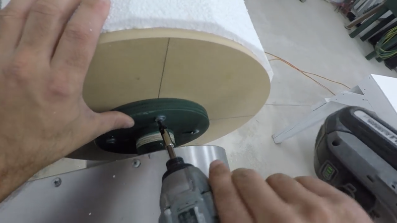
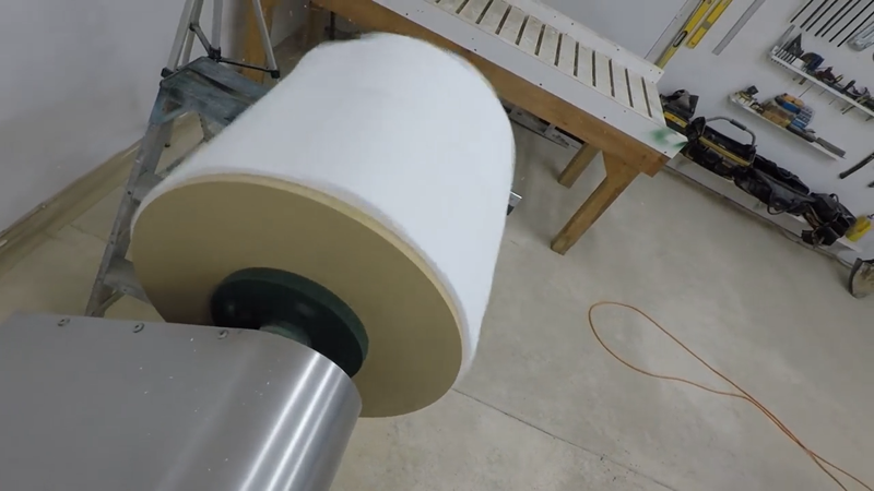
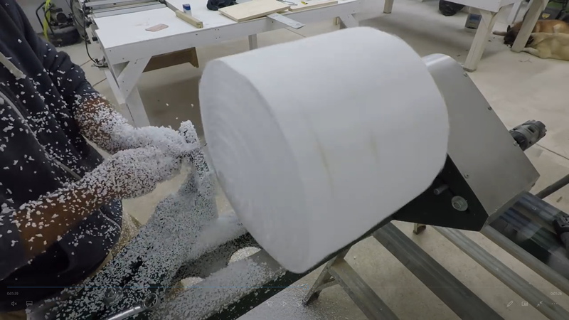
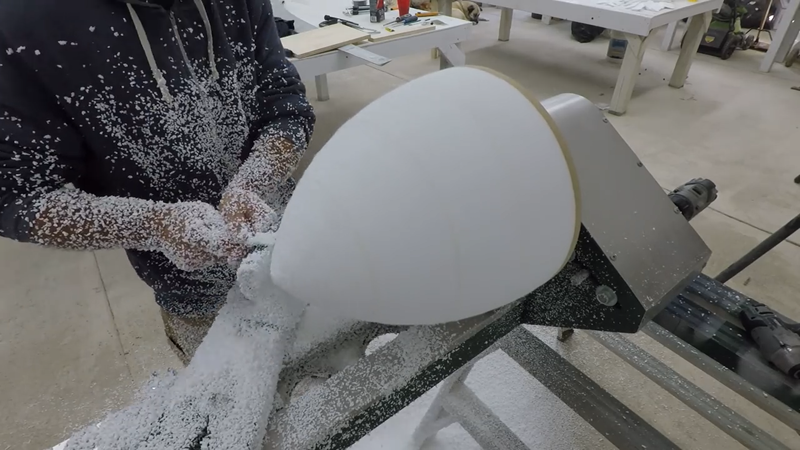
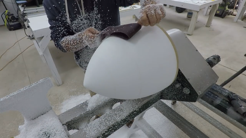
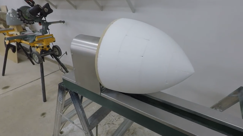
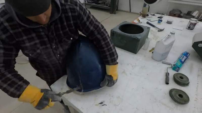
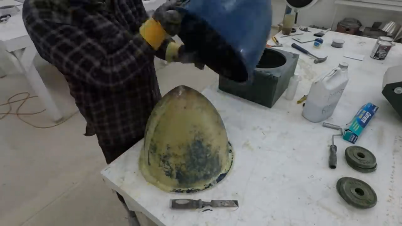
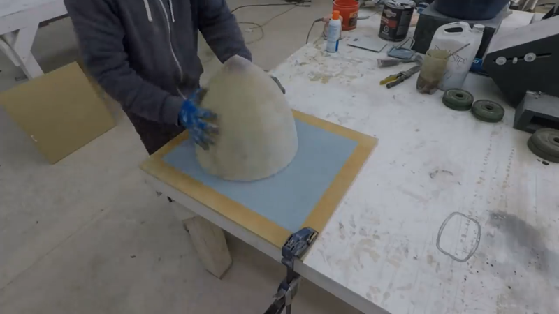
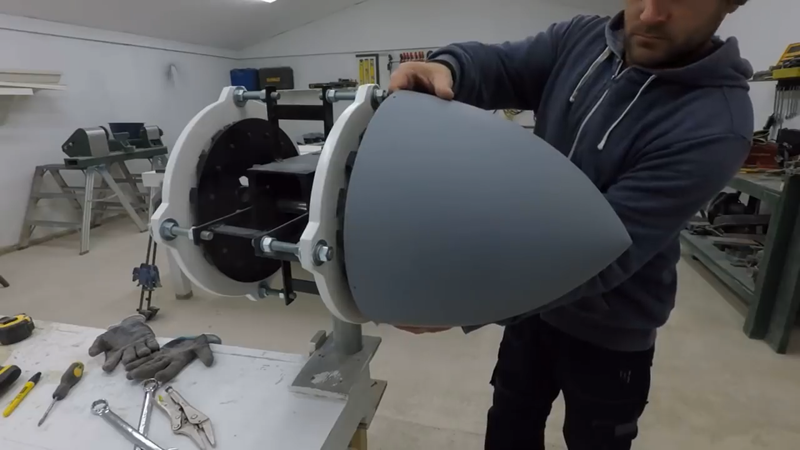
Most DIY turbines don't include one, but I decided to make a fiberglass nose cone to finish off the rotor. First I made a foam plug using my DIY benchtop lathe. A plug is just a model of the part that needs to be cast, which is used to create a negative mold for casting. I covered the plug with filler, sanded it smooth and then painted it.
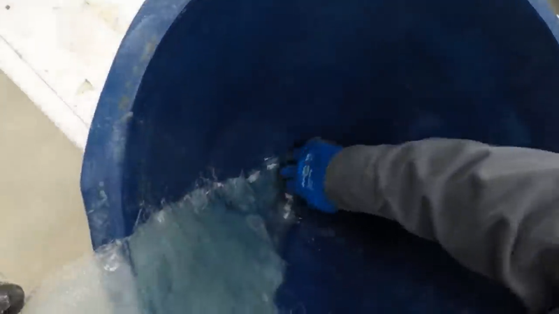
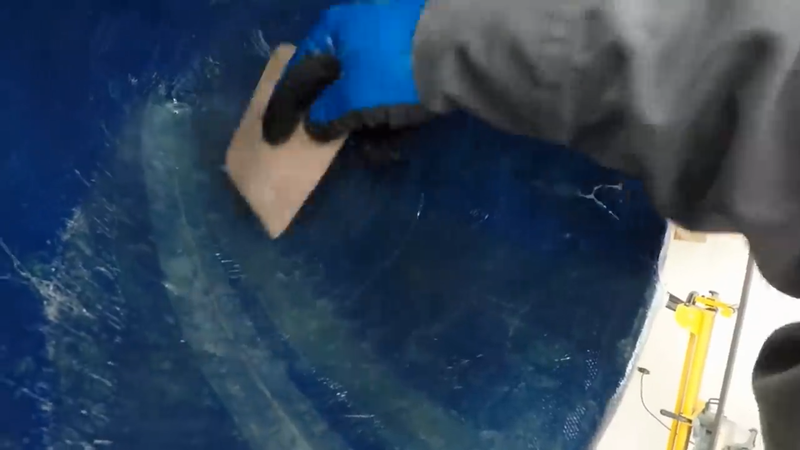
I then covered it with petroleum jelly and put approx. 6 layers of fiberglass cloth and polyester resin over it to make the mold and let it cure. The next day I removed the fiberglass mold from the plug, painted it, and used it to cast the actual nose cone with more fiberglass and polyester resin. In retrospect, I should have used a gel coat on the mold's inside surface or made fiberglass and silicone sock and mother molds because there was a risk of the resin in the cast crosslinking and adhering to the resin in the mold as it cured. Lucky, it didn't this time.
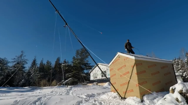
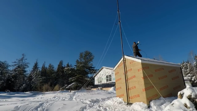
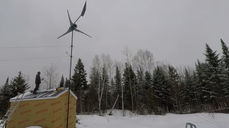
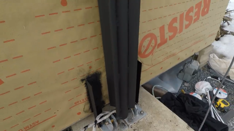
At this point the turbine is ready to install, but I still had to build a tower. It was made with 30 ft of 2.5" schedule 80 pipe, two pieces 15 ft long welded together in the middle. I notched the bottom end to receive a 1" pipe that would form part of the hinge that would be anchored to the reinforced concrete base below the tower and allow it to be raised and lowered with a 1500 lb winch. I made anchor brackets for attaching guy wires and welded them over the joint in the middle of the tower and another set a few inches below where the tip of the blades would be, so there would be two sets of guy wires anchoring the tower in all four directions.
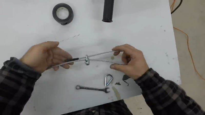
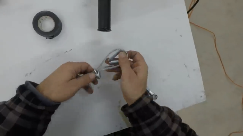
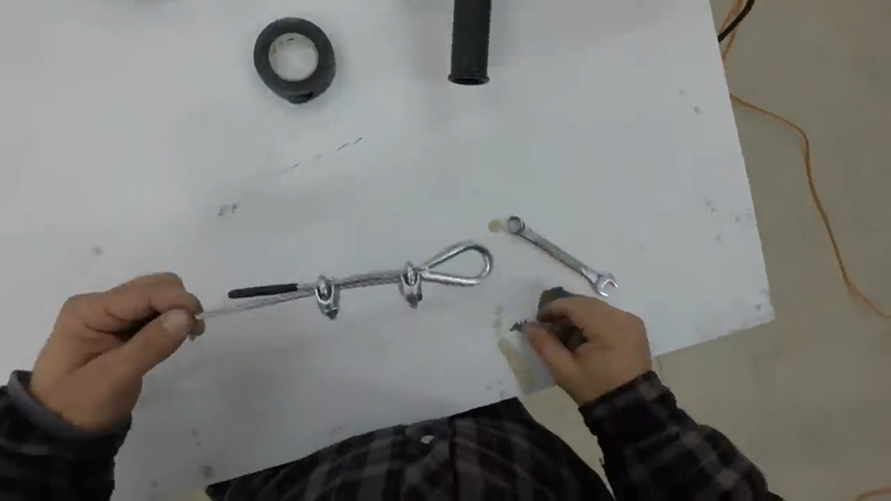
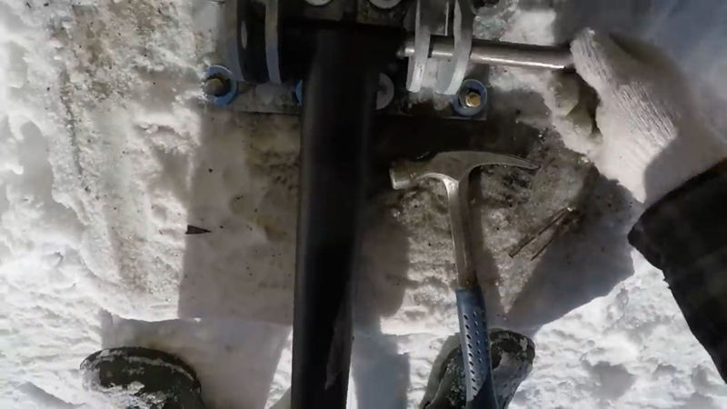
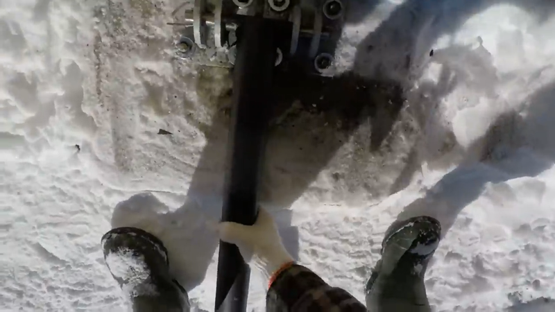
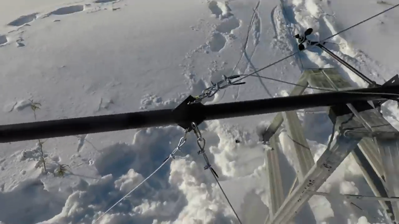
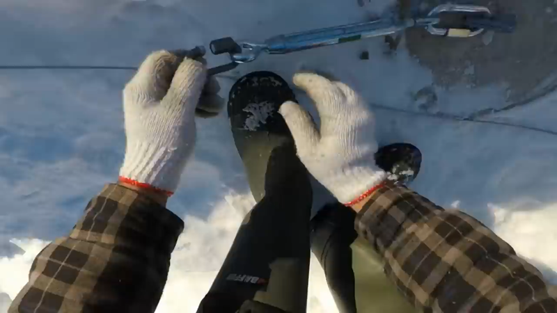
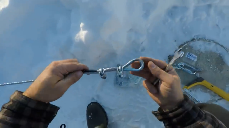
I welded the tower and brackets together in the workshop, then took some measurements outside and calculated the rough length of the guy wires so that I could cut and prep those. I used 5/16" stainless steel aircraft cables for the guy wires, with two cable clamps and a thimble on each end - I only prepped one end in the workshop and finished the other once the turbine was raised and I could cut it to the exact length needed. Something to note for those who've never used wire clamps before, is to make sure the saddle of the clamp is on the live (long, load) side of the wire as shown below - 'never saddle a dead horse', as they say. If the saddle is on the short side of the wire, then it could slip under load.
The location I picked for the tower was right at the end of my utility shed. The roof provided a sturdy anchor point for the winch, which was high enough to eliminate the need for a gin pole to raise the tower.
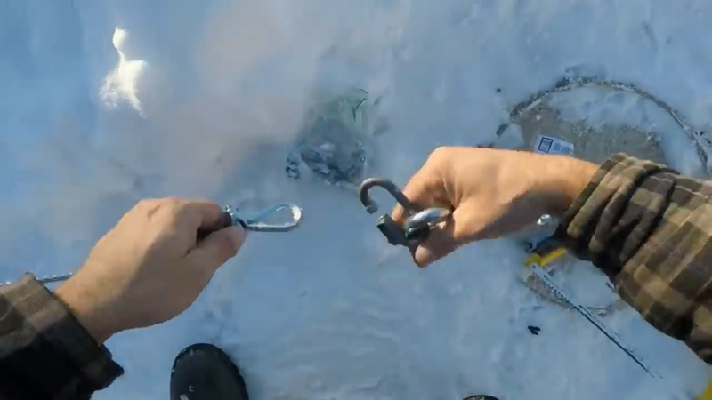
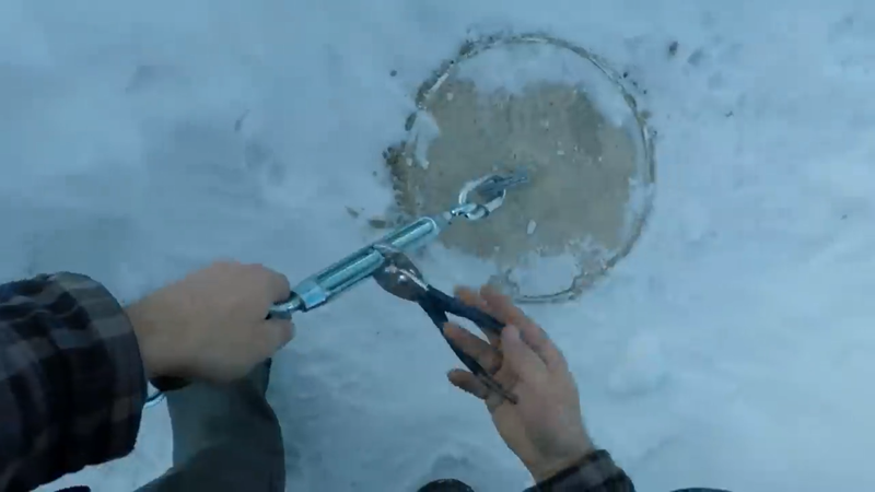
A few months prior to the turbine build, I had dug 2'x3ft deep holes in the ground to pour the concrete guy anchors so they would be fully cured and ready for the installation, so all I had to do was line up the tower with the anchors in the concrete base, insert the hinge pin, lift the tower (without the turbine) into position and then cut the guy wires to length and clamp the ends while the tower is still attached to the winch, and connect them to their ground anchors with turnbuckles.
Once I had the guy wires set, I loosened them all and disconnected the one wire that ran parallel to the winch cable so that I could lower the tower again. Theoretically the other three wires can stay connected as long as they're close to the same elevation and length.
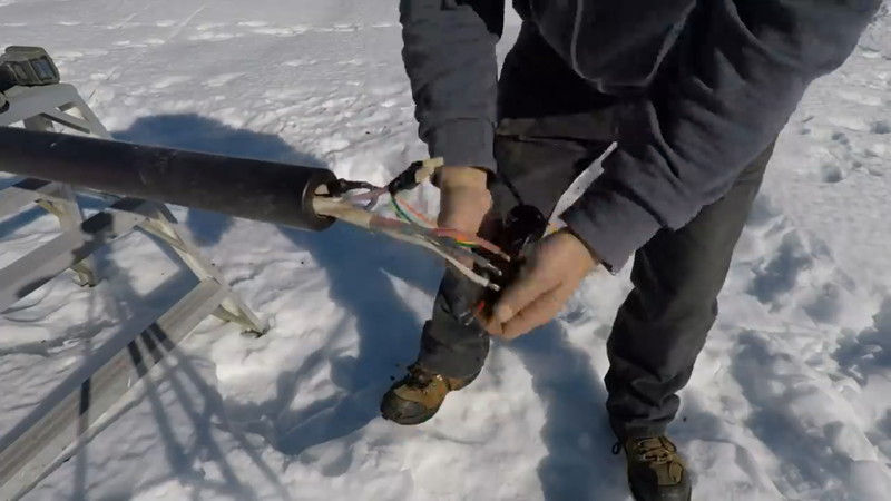
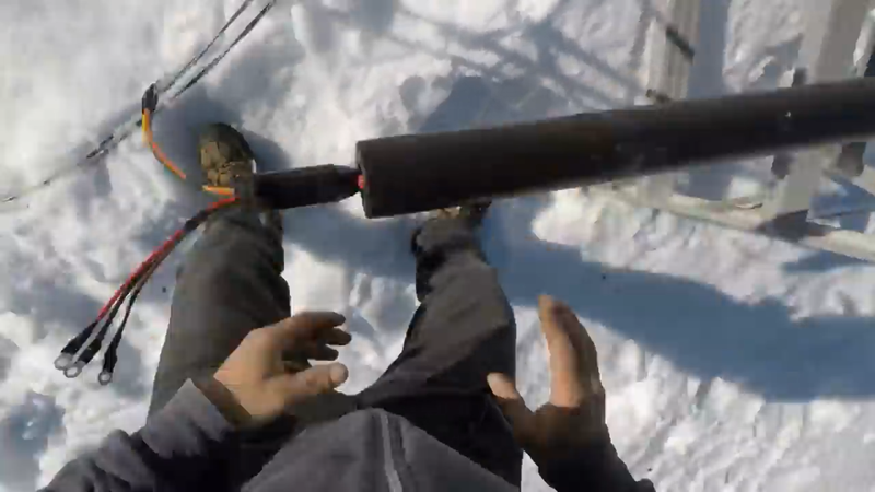
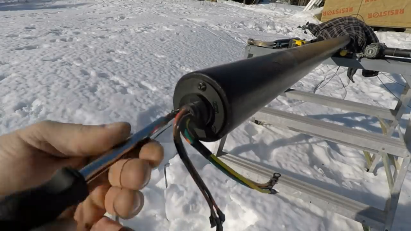
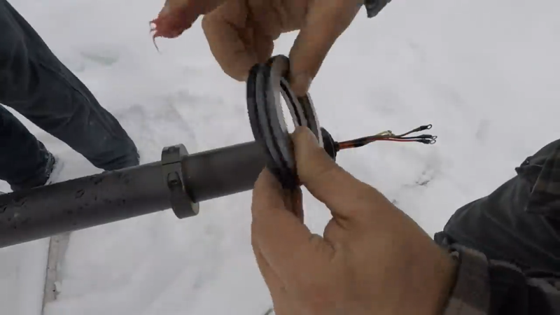
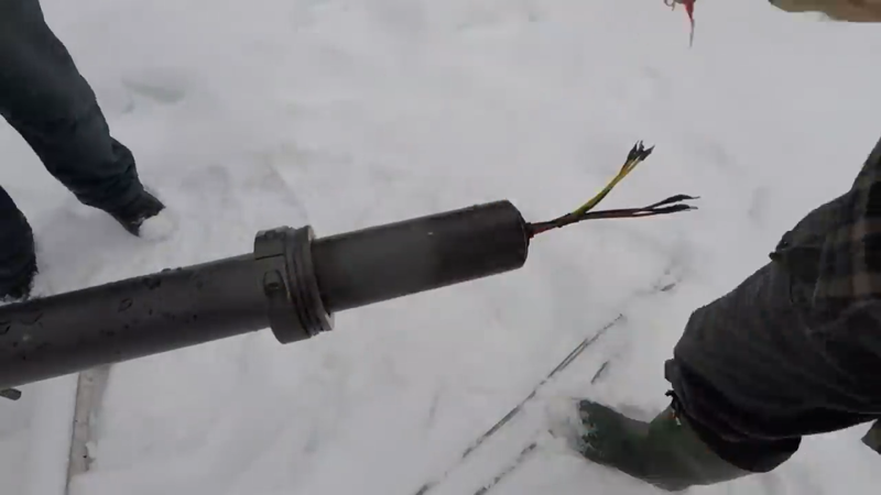
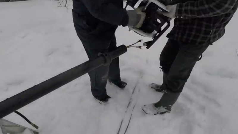
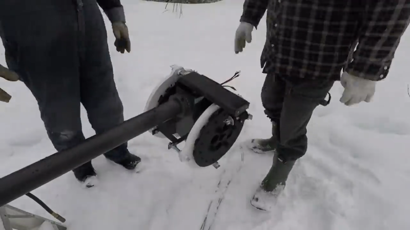
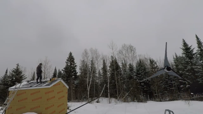
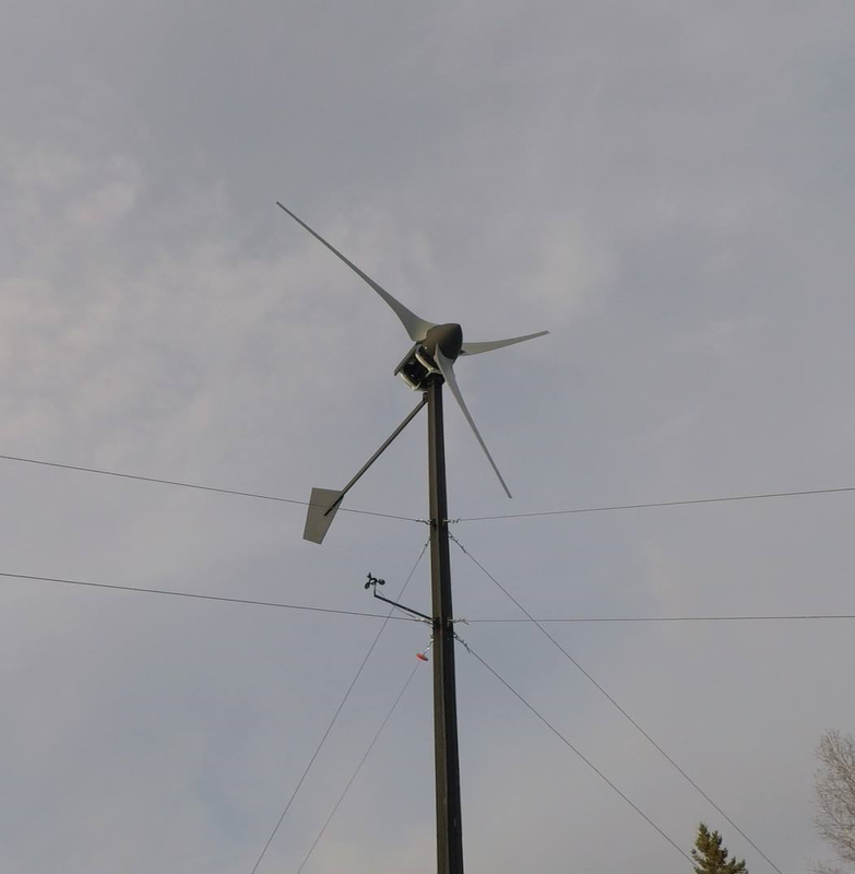
I then fished the transmission cables from the charge controller in the house, through the tower and out of the top of it. To help keep the cables from twisting up in the tower over time, I installed a slip ring. This device transmits power from the generator to the transmission cables using brushes and cylindrical contacts that the brushes rotate around, like the brushes and commutator in some power tool motors. It has 6 input wires and 6 output wires (one wire per phase), each capable of handling 30 amps continuously. After the slip ring was installed, I installed a 2.5" split locking collar and axial bearing on the tower for the turbine to rest on, then my dad gave me a lift to install the turbine onto the tower. The generators were then wired to the split ring and the tail was installed.
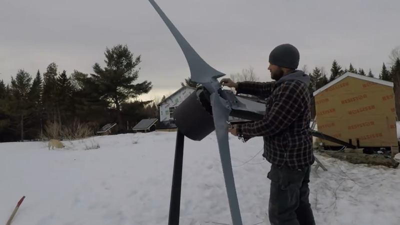
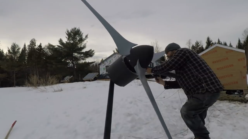
Finally it was time to install the blade set. I bolted the hub to the rotor shaft and then gave the blades a few spins by hand to determine if there was a heavy side or not, which would be indicated by that side always coming to a rest while pointing to the ground. There was a heavy side, so I added a couple more nuts to the mounting bolts on the opposite side and that balanced things out. I had also installed an anemometer a few inches below the blades to measure real time wind speed with the power output from the controller.
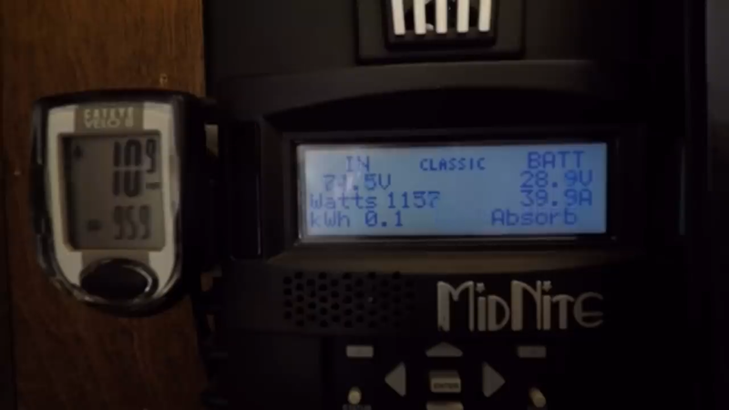
After turning on the electrical brake in the house to keep the blades from spinning until I was ready, the turbine was raised into the air and the guy wires were anchored in place. Then I turned the Midnite Classic charge controller on in the house and turned the turbine brake off to begin charging my battery bank. The turbine began spinning almost immediately after turning off the break. I don't know what the start up speed is because it's too low for the anemometer to measure (only whole numbers). The cut-in speed was very low, around 5 mph and it began charging. The tower is about 20 ft too low for this area and it gets a lot of turbulence off the trees as a result, but I've seen the occasional gust of 28-30 mph generate between 2500-3000 watts. On avg with the 10 mph mean annual wind speed, here, it produces around 500 watts per hour, or ~500 kWh per month. That's a majority of the energy that a bachelor like myself uses, and a good chunk of the energy demand of a typical family. You can watch the power performance video here showing slightly more than 2600 watts being produced in a 24 mph wind. |
AuthorJames Biggar Archives
March 2023
Categories |





 RSS Feed