Solar HVAC 2: Combining Desiccant Dehumidification W/ Evaporative Cooling
|
|
Share this page with your friends:
|
The testing and information presented below was done to approximate the effectiveness of using desiccant dehumidification with evaporative cooling to dehumidify and cool an air stream produced in a small co-generative solar HVAC system.
Introduction/Hypothesis:
As described in the previous desiccant rotor tests, this research is aimed at developing an efficient, low power co-generative solar HVAC system for humid regions by combining solar thermal and photovoltaics, desiccant dehumidification and evaporative cooling technologies. If you haven't reviewed the desiccant rotor tests, I recommend checking those out first for more context before reading further.
With the latest desiccant rotor tests being successful, it's time to incorporate an evaporative cooler; the drier warm air from the rotor should be able to absorb more water from the cooler as it passes through, and cool it to within the standard optimal temperature range of 70-75°F/21-24°C. (Unlike conventional air conditioners, evaporative coolers use water's enthalpy of vaporisation for transferring heat instead of a compressed refrigerant, so the exhaust temperature from an evaporative cooler will only get as low as the dew point temperature at best, though generally it's around 10°F warmer for most units. To maintain a comfortable room temperature in a living or work space, evaporative coolers circulate air through the space much more quickly, but do this using much less energy. Because of this, evaporative coolers are rated in CFM's, vs BTU's for air conditioners).
|
Methods:
The following setup is quick and dirty, but good enough for collecting the data needed for designing a refined prototype to scale: The dehumidifier's (desiccant rotor assembly) regeneration chamber intake port was connected to the hot air exhaust port of a wall mounted 'waveform matrix' solar air heater via a 3" duct, and the exhaust from the regen. chamber was directed outside via another duct and a 12V/100CFM fan. A 500W PCT electric heating element controlled by a thermal snap switch was incorporated in the regen. duct for backup heat to dry the desiccant during cloudy conditions. Fresh outdoor air was directed to the dehumidification chamber via a 3" duct, and the exhaust port was connected directly to the evaporative cooler's intake port. |
|
The evaporative cooler was a very simple polyisocyanurate foam construction with one acrylic side for viewing purposes. The cooling chamber measures approx. 6"x6"x6" and was located just above the water storage/pump compartment, which held close to 1L and was lined with plastic to prevent leaks. 8 layers of rigid furnace filter stacked horizontally in the cooling chamber was used as the cooling media. A small 120V aquarium pump was used to pump cool water from the storage compartment to the top of the filter media and disperse it via perforated rubber tubing, where it's then naturally pulled down through the media vertically by gravity as the air stream was pulled from the dehumidifier and through the cooling chamber horizontally by a 12V/100CFM axial fan mounted at the exhaust port of the evaporative cooler.
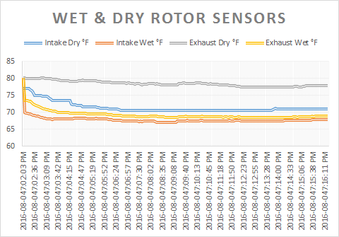
A small 6"x6"x1" heat exchanger was incorporated between the dehumidifier and the evaporative cooler prior to a second set of tests to see if the exhaust temperature could be lowered further. The pump in the evaporative cooler pumped water from the storage compartment to the heat exchanger first, and then to the perforated rubber tubing above the cooler's filter media.
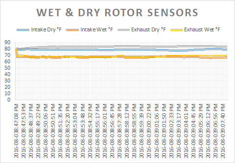
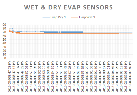
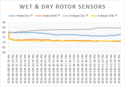
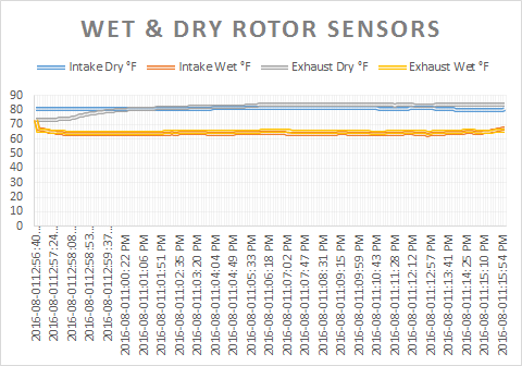
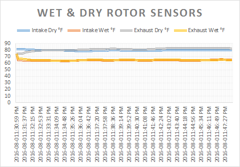
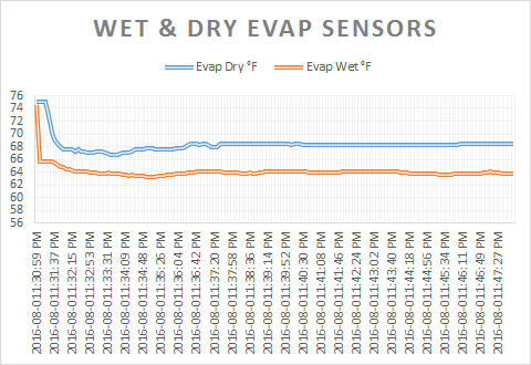
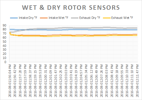
For comparison, tests were done during weather conditions with both low and high ambient relative humidity. Temperature and relative humidity was measured using the dry/wet bulb method with NTC sensors located in the ducts just before the dehumidification chamber, between the dehumidification chamber and the evaporative cooler intake, and at the evaporative cooler's exhaust. The data was logged using PC software and Microsoft Excel.
A small 6"x6"x1" heat exchanger was incorporated between the dehumidifier and the evaporative cooler prior to a second set of tests to see if the exhaust temperature could be lowered further. The pump in the evaporative cooler pumped water from the storage compartment to the heat exchanger first, and then to the perforated rubber tubing above the cooler's filter media.
For comparison, tests were done during weather conditions with both low and high ambient relative humidity. Temperature and relative humidity was measured using the dry/wet bulb method with NTC sensors located in the ducts just before the dehumidification chamber, between the dehumidification chamber and the evaporative cooler intake, and at the evaporative cooler's exhaust. The data was logged using PC software and Microsoft Excel.
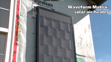
The solar heater
|
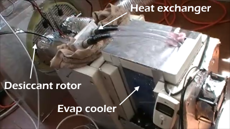
The configuration
|
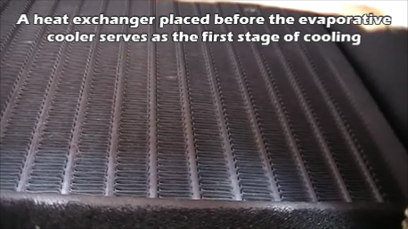
The heat exchanger
|
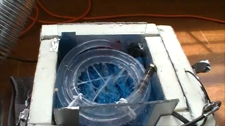
The evaporative cooler
|
|
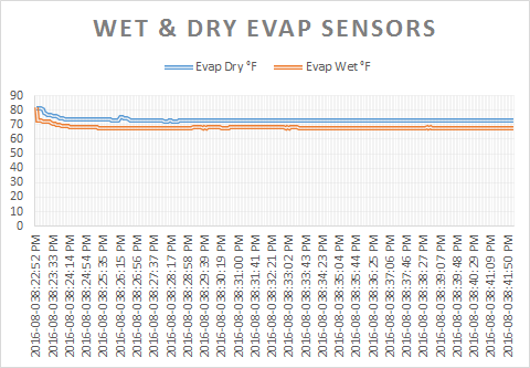
Results:
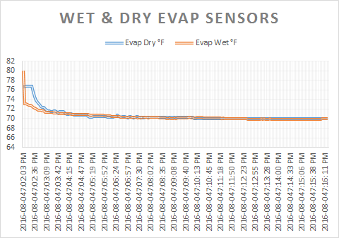
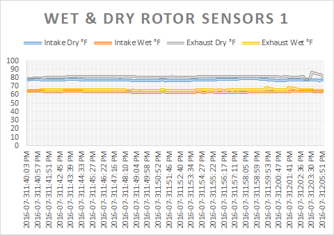
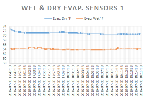
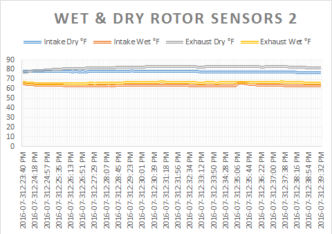
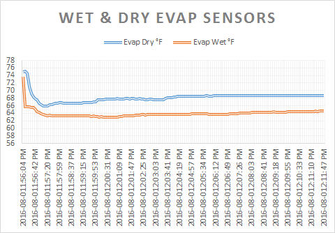
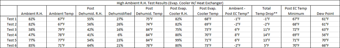
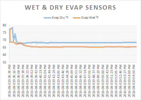
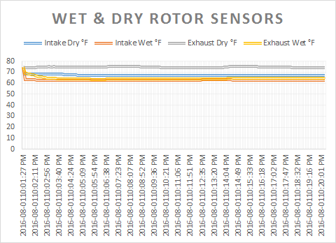
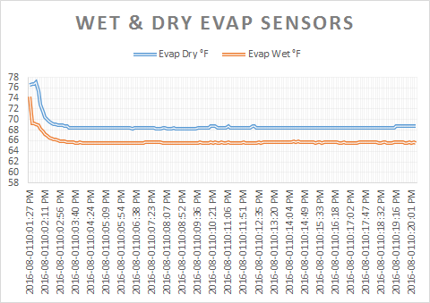
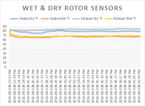
The evaporative cooler performed well when the air stream was dried below 60% relative humidity. It achieved temperature drops of up to 14°F with a minimum as low as 66°F. This is below the optimum range of 70-75°F, which means that a lower air flow rate can be used to decrease electrical power consumption further while maintaining a comfortable temperature. The desiccant rotor still absorbed some heat from the solar heater and transferred it to the dehumidification chamber, but the heat exchanger seemed to help lower the exhaust temperature by a few degrees when compared to the tests that didn't incorporate it. The dehumidifier performed well when the relative humidity was above 50% - below this the desiccant's ability to adsorb moisture was dramatically lowered, but that's almost inconsequential because (as mentioned previously) the effectiveness of the evaporative cooler is well within a reasonable range when the ambient humidity is below that level. The wall mounted solar heater struggled to provide sufficient heat during partly cloudy conditions, due to the high angle of incidence to the sun at this time of year - a wall mounted heater is generally better suited for winter conditions when the sun is lower in the sky. With a proper angle of incidence, the solar heater should provide up to 20% more heat energy and adequately dry the desiccant rotor, but this will be determined definitively at a later date. Other possible changes include using a synthetic substrate for the desiccant rotor in place of aluminium to lower the rotor's overall thermal conductivity and minimise heat transfer from the regeneration chamber to the dehumidification chamber. The rotor's depth can be increased again to widen the operating R.H. range, and silica gel could replace the molecular sieve beads, as it will adsorb slightly more moisture in low humidity conditions. I've also been considering incorporating another heat exchanger to investigate making better use of the waste heat exhausted from the dehumidifier's regen chamber by storing it for DHW purposes - condensation from both heat exchangers in extremely humid conditions could also be collected to help replenish some of the water that the evaporative cooler uses. Given that the north east US/Canada is generally mild/wet, the water source for the evaporative cooler could be harvested rain water, stored underground or in a crawl space out of direct sunlight to help keep it cool. There are lots of possibilities, this research is only scratching the surface. |
|
Low Ambient Relative Humidity Tests

|
Test 1
|
Test 2
|
|
|
|

| ||||||||

|
Test 1
|
Test 2
|
Test 3
|
|

|
|
|
|
| ||||||||||||
High Ambient Relative Humidity Tests

|
Test 1
|
Test 2
| ||||||||||||


|
Test 1
|
Test 2
|
Test 3
|
|
|
|
|
|
| ||||||||||||
|
Test 4
|
Test 5
|
Test 6
| ||||||||||||||||||